DTC P0112 / P0113
Precautions: General safety (00)
DTC Detecting Condition and Trouble Area
| DTC detecting condition | Trouble area |
|---|---|
|
P0112: Intake Air Temperature Sensor 1 Circuit Low Output voltage of IAT sensor-1 signal circuit is lower than 0.02 V for 5 sec. (3 D/C detection logic) |
•IAT sensor-1 and/or its circuit
•ECM |
|
P0113: Intake Air Temperature Sensor 1 Circuit High Output voltage of IAT sensor-1 signal circuit is higher than 4.98 V for 5 sec. (3 D/C detection logic) |
Circuit Diagram
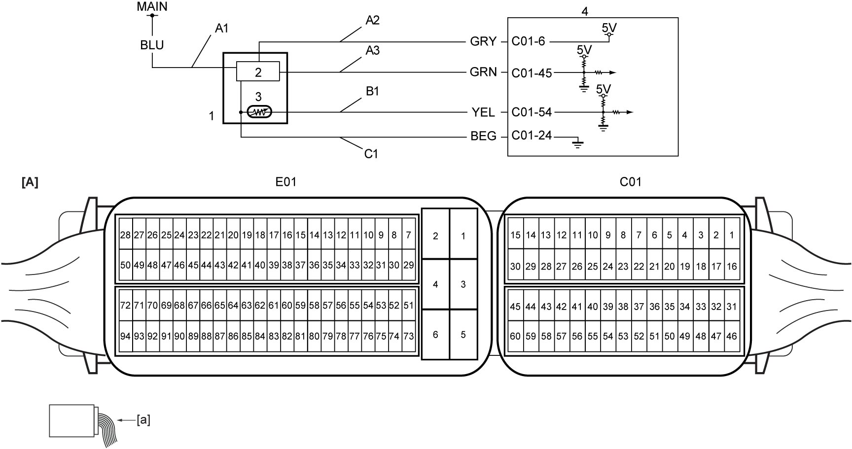
| [A]: | ECM connector (View: [a]) | B1: | IAT sensor-1 signal circuit | 3. | IAT sensor-1 |
| A1: | MAF sensor power supply circuit | C1: | MAF sensor with IAT sensor-1 ground circuit | 4. | ECM |
| A2: | MAF sensor reference voltage circuit | 1. | MAF sensor with IAT sensor-1 | ||
| A3: | MAF sensor signal circuit | 2. | MAF sensor |
DTC Confirmation Procedure
1)Warm up engine to normal operating temperature.
2)Run engine at idle speed for 10 sec.
DTC Troubleshooting
| Step | Action | Yes | No |
|---|---|---|---|
| 1 |
Was “Engine and Emission Control System Check” performed?
|
Go to Step 2.
|
|
| 2 |
IAT sensor-1 signal circuit and ground circuit check
1)With ignition “OFF”, disconnect “C01” and “E01” connectors of ECM and MAF sensor with IAT sensor-1 connector.
2)Check for proper terminal connection to “C01” and “E01” connectors and MAF sensor with IAT sensor-1 connector.
3)If connections are OK, check the following points.
•Resistance of “B1” and “C1” circuits: less than 1 Ω
•Resistance between each of “B1” and “C1” circuits and ground: infinity •Resistance between “B1” circuit terminal and other terminal at MAF sensor with IAT sensor-1 connector: infinity •Resistance between “C1” circuit terminal and other terminal at MAF sensor with IAT sensor-1 connector: infinity •Voltage of “B1” and “C1” circuits: approx. 0 V (When ignition is “ON”) Is check result OK?
|
Go to Step 3.
|
Repair or replace defective wire harness.
|
| 3 |
IAT sensor-1 check
1)Check IAT sensor-1.

Is check result OK?
|
Replace ECM and recheck DTC.
|
Replace MAF sensor with IAT sensor-1.
|