DTC P2135
Precautions: General safety (00)
DTC Detecting Condition and Trouble Area
| DTC detecting condition | Trouble area |
|---|---|
|
P2135: Throttle / Pedal Position Sensor / Switch “A” / “B” Voltage Correlation Difference between TP sensor (main) signal voltage and TP sensor (sub) signal voltage is higher than specified value. (1 D/C detection logic) |
•TP sensor and/or its circuit
•Electric throttle body assembly •ECM |
Circuit Diagram
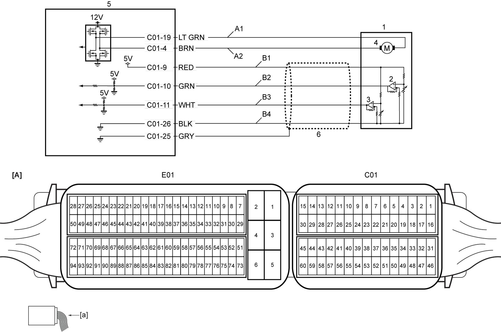
| [A]: | ECM connector (View: [a]) | B3: | TP sensor (sub) signal circuit | 4. | Throttle actuator |
| A1: | Throttle actuator control circuit (close) | B4: | TP sensor ground circuit | 5. | ECM |
| A2: | Throttle actuator control circuit (open) | 1. | Electric throttle body assembly | 6. | Shield wire |
| B1: | TP sensor power supply circuit | 2. | TP sensor (main) | ||
| B2: | TP sensor (main) signal circuit | 3. | TP sensor (sub) |
DTC Confirmation Procedure
NOTE:
Check that the following DTCs are not detected in this “DTC Confirmation Procedure”.
•TP sensor (P0122, P0123, P0222 and P0223)
•System voltage (P0560, P0562 and P0563)
•System voltage (P0560, P0562 and P0563)
1)Set ignition “ON”.
2)Keep accelerator pedal at fully depressed position for 2 sec.
3)Release accelerator pedal for 2 sec
4)Repeat Step 2) – 3) 3 times.
DTC Troubleshooting
| Step | Action | Yes | No |
|---|---|---|---|
| 1 |
Was “Engine and Emission Control System Check” performed?
|
Go to Step 2.
|
|
| 2 |
Wire harness check
1)Check the following points.
•“B1”, “B2” and “B4” circuits: Refer to Step 2 – 4 under DTC P0122 / P0123:K14C.
•“B3” circuit: Refer to Step 4 under DTC P0222 / P0223:K14C. Is check result OK?
|
Go to Step 3.
|
Repair or replace defective wire harness.
|
| 3 |
TP sensor check
1)Check TP sensor for performance referring to “TP Sensor Performance Check” under Electric Throttle Body Assembly On-Vehicle Inspection:K14C.
Is check result OK?
|
Replace ECM and recheck DTC.

|
Replace electric throttle body assembly.
|