Inspection of ECM and Its Circuits
Precautions: General safety (00)
Voltage Check
NOTE:
•As each terminal voltage is affected by battery voltage, check that battery voltage is 11 V or more when ignition is “ON”.
•Voltage with asterisk (*) cannot be measured with voltmeter because it is pulse signal. Use oscilloscope for its check.
•Before performing this inspection, read “Precautions for ECM Circuit Inspection” under Precautions for Engine (K14C).
•Voltage with asterisk (*) cannot be measured with voltmeter because it is pulse signal. Use oscilloscope for its check.
•Before performing this inspection, read “Precautions for ECM Circuit Inspection” under Precautions for Engine (K14C).
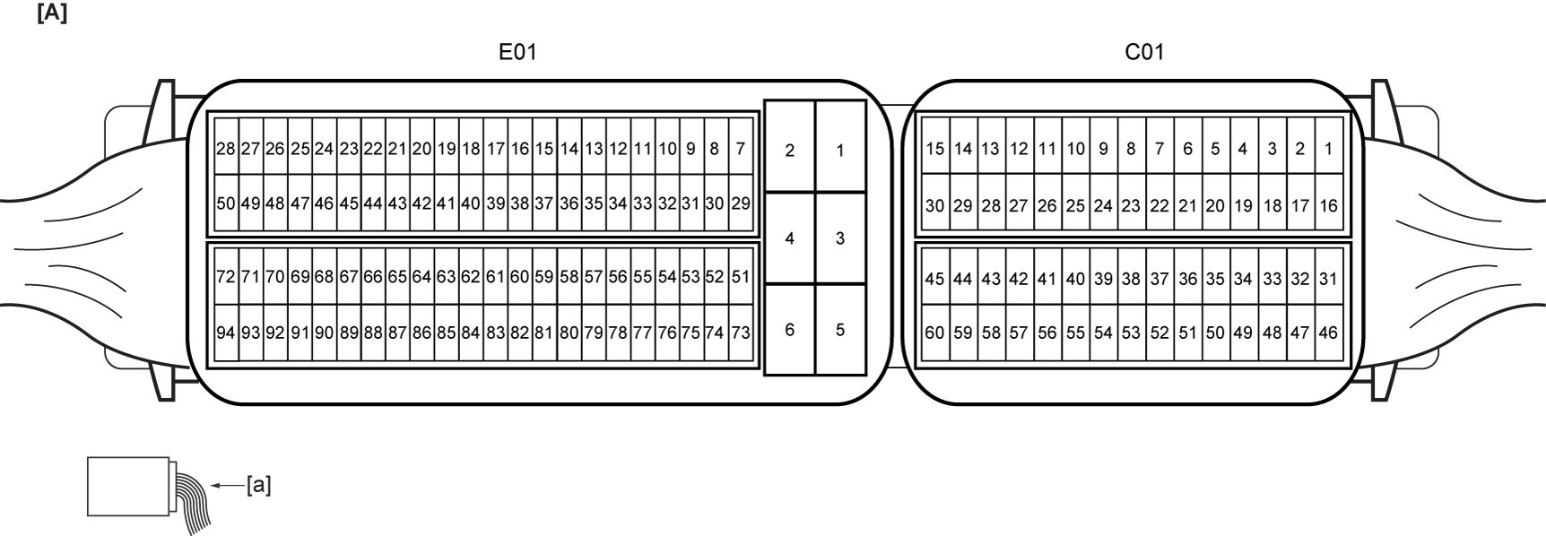
| [A]: | ECM connector (View: [a]) |
“C01” connector
| Terminal No. | Wire color | Circuit | Normal voltage | Condition |
|---|---|---|---|---|
| C01-1* | WHT | Fuel injector No.2 drive circuit (low side) | Refer to reference waveform. | |
| C01-2* | GRY | WGV-VSV drive circuit | 10 to 14 V | Ignition: “ON” |
| Refer to reference waveform. WGV-VSV signal |
||||
| C01-3* | GRN | OCV drive circuit | 10 to 14 V | Ignition: “ON” |
| Refer to reference waveform. OCV signal |
||||
| C01-4* | BRN | Throttle actuator drive circuit (open) | Refer to reference waveform. Throttle actuator signal |
|
| C01-5* | YEL | ABV-VSV drive circuit | 10 to 14 V | Ignition: “ON” |
| Refer to reference waveform. ABV-VSV signal |
||||
| C01-6 | GRY | MAF sensor reference voltage signal | 4.5 to 5.5 V | Ignition: “ON” |
| C01-7 | PNK | Boost pressure sensor power supply circuit | 4.5 to 5.5 V | Ignition: “ON” |
| C01-8 | LT BLU | Fuel pressure sensor and MAP sensor power supply circuit | 4.5 to 5.5 V | Ignition: “ON” |
| C01-9 | RED | TP sensor power supply circuit | 4.5 to 5.5 V | Ignition: “ON” |
| C01-10 | GRN | TP sensor (main) signal circuit | 0.8 to 1.0 V | Ignition: “ON” Accelerator pedal: Released |
| 4.3 to 4.5 V | Ignition: “ON” Accelerator pedal: Fully depressed |
|||
| C01-11 | WHT | TP sensor (sub) signal circuit | 4.0 to 4.2 V | Ignition: “ON” Accelerator pedal: Released |
| 0.5 to 0.7 V | Ignition: “ON” Accelerator pedal: Fully depressed |
|||
| C01-12* | BRN | HO2S-2 signal circuit | Refer to reference waveform. HO2S-2 signal |
|
| C01-13 | BEG | HO2S-2 shield ground circuit | Below 0.3 V | Ignition: “ON” |
| C01-14* | WHT | CAN (low) communication circuit 2 | Refer to reference waveform. CAN communication signal |
|
| C01-15* | YEL | HO2S-1 heater drive circuit | Refer to reference waveform. HO2S-1 heater signal and HO2S-2 heater signal |
|
| C01-16* | BRN | Fuel injector No.2 drive circuit (high side) | Refer to reference waveform. Fuel injector signal |
|
| C01-17* | BLK | EVAP canister purge valve drive circuit | 10 to 14 V | Ignition: “ON” |
| Refer to reference waveform. EVAP canister purge valve signal |
||||
| C01-18 | — | — | — | — |
| C01-19* | LT GRN | Throttle actuator drive circuit (close) | Refer to reference waveform. Throttle actuator signal |
|
| C01-20* | RED | CMP sensor signal circuit | Approx. 0 V or 4 to 5 V | Ignition: “ON” |
| Refer to reference waveform. CMP sensor signal and CKP sensor signal |
||||
| C01-21 | BLU | ECT sensor signal circuit | 3.2 to 3.6 V | Ignition: “ON” ECT: 0 °C (32 °F) |
| 1.0 to 1.4 V | Ignition: “ON” ECT: 50 °C (122 °F) |
|||
| 0.2 to 0.5 V | Ignition: “ON” ECT: 100 °C (212 °F) |
|||
| C01-22 | RED | Fuel pressure sensor signal circuit | Approx. 1.0 V | Engine: Idle speed after warming up Reference fuel rail pressure: 3 MPa (30.6 kgf/cm2, 435 psi, 30 bar) |
| Approx. 1.5 V | Engine: Running at 4,000 rpm after warming up Reference fuel rail pressure: 4.6 MPa (46.9 kgf/cm2, 667 psi, 46 bar) |
|||
| C01-23 | BEG | ECT sensor and boost pressure sensor with IAT sensor-2 ground circuit | Below 0.3 V | Ignition: “ON” |
| C01-24 | BEG | MAF sensor with IAT sensor-1 ground circuit | Below 0.3 V | Ignition: “ON” |
| C01-25 | GRY | TP sensor shield ground circuit | Below 0.3 V | Ignition: “ON” |
| C01-26 | BLK | TP sensor ground circuit | Below 0.3 V | Ignition: “ON” |
| C01-27 | YEL | HO2S-2 ground circuit | Below 0.3 V | Ignition: “ON” |
| C01-28 | LT BLU | HO2S-1 shield ground circuit | Below 0.3 V | Ignition: “ON” |
| C01-29* | RED | CAN (high) communication circuit 2 | Refer to reference waveform. CAN communication signal |
|
| C01-30* | RED | HO2S-2 heater drive circuit | Refer to reference waveform. HO2S-1 heater signal and HO2S-2 heater signal |
|
| C01-31* | BLU | Fuel injector No.3 drive circuit (high side) | Refer to reference waveform. Fuel injector signal |
|
| C01-32* | YEL | Fuel injector No.1 drive circuit (low side) | Refer to reference waveform. | |
| C01-33* | GRN | Fuel injector No.1 drive circuit (high side) | Refer to reference waveform. Fuel injector signal |
|
| C01-34* | RED | High pressure fuel pump drive circuit | Refer to reference waveform. High pressure fuel pump signal |
|
| C01-35 | GRY | CMP sensor ground circuit | Below 0.3 V | Ignition: “ON” |
| C01-36 | — | — | — | — |
| C01-37* | WHT | Knock sensor signal circuit 1 | 1 to 2 V | Engine: Idle speed |
| Refer to reference waveform. Knock sensor signal |
||||
| C01-38 | BEG | Fuel pressure sensor ground circuit | Below 0.3 V | Ignition: “ON” |
| C01-39 | PPL | Boost pressure sensor signal circuit | Approx. 2.0 V | Engine: Idle speed after warming up Reference boost pressure: 101 kPa (1.03 kgf/cm2, 14.6 psi, 1.01 bar) |
| Refer to reference waveform. MAF sensor signal, boost pressure sensor signal and MAP sensor signal |
||||
| C01-40 | BRN | MAP sensor signal circuit | Approx. 2.0 V | Ignition: “ON” |
| Approx. 0.8 V | Engine: Idle speed after warming up Barometric pressure: 101 kPa, 758 mmHg |
|||
| Refer to reference waveform. MAF sensor signal, boost pressure sensor signal and MAP sensor signal |
||||
| C01-41* | GRN | Ignition coil No.2 drive circuit | Approx. 0 V | Ignition: “ON” |
| Refer to reference waveform. | ||||
| C01-42* | BRN | Ignition coil No.3 drive circuit | Approx. 0 V | Ignition: “ON” |
| Refer to reference waveform. | ||||
| C01-43* | RED | HO2S-1 signal circuit | Refer to reference waveform. HO2S-1 signal |
|
| C01-44 | — | — | — | — |
| C01-45* | GRN | MAF sensor signal circuit | 0.1 to 1.0 V | Ignition: “ON” |
| Refer to reference waveform. MAF sensor signal, boost pressure sensor signal and MAP sensor signal |
||||
| C01-46* | RED | Fuel injector No.3 drive circuit (low side) | Refer to reference waveform. | |
| C01-47* | LT BLU | Fuel injector No.4 drive circuit (low side) | Refer to reference waveform. | |
| C01-48* | LT GRN | Fuel injector No.4 drive circuit (high side) | Refer to reference waveform. Fuel injector signal |
|
| C01-49 | BLU | High pressure fuel pump power supply circuit | 4.5 to 5.5 V | Ignition: “ON” |
| C01-50* | PNK | CKP sensor signal circuit | Approx. 0 V or 4 to 5 V | Ignition: “ON” |
| Refer to reference waveform. | ||||
| C01-51 | GRY | CKP sensor ground circuit | Below 0.3 V | Ignition: “ON” |
| C01-52* | BLU | Knock sensor signal circuit 2 | 1 to 2 V | Engine: Idle speed |
| Refer to reference waveform. Knock sensor signal |
||||
| C01-53 | BEG | MAP sensor ground circuit | Below 0.3 V | Ignition: “ON” |
| C01-54 | YEL | IAT sensor-1 signal circuit | 2.2 to 2.6 V | Ignition: “ON” IAT-1: 20 °C (68 °F) |
| 1.3 to 1.7 V | Ignition: “ON” IAT-1: 40 °C (104 °F) |
|||
| C01-55 | GRN | IAT sensor-2 signal circuit | 2.2 to 2.6 V | Ignition: “ON” IAT-2: 20 °C (68 °F) |
| 1.3 to 1.7 V | Ignition: “ON” IAT-2: 40 °C (104 °F) |
|||
| C01-56* | YEL | Ignition coil No.1 drive circuit | Approx. 0 V | Ignition: “ON” |
| Refer to reference waveform. | ||||
| C01-57* | PNK | Ignition coil No.4 drive circuit | Approx. 0 V | Ignition: “ON” |
| Refer to reference waveform. | ||||
| C01-58 | GRN | HO2S-1 ground circuit | Below 0.3 V | Ignition: “ON” |
| C01-59 | — | — | — | — |
| C01-60* | BLU | Generator LIN communication circuit | Refer to reference waveform. Generator LIN communication signal |
|
“E01” connector
| Terminal No. | Wire color | Circuit | Normal voltage | Condition |
|---|---|---|---|---|
| E01-1 | GRN | Main power supply circuit 3 | 10 to 14 V | Ignition: “ON” |
| E01-2 | BLK | ECM ground circuit 3 | Below 0.3 V | Ignition: “ON” |
| E01-3 | GRN | Main power supply circuit 2 | 10 to 14 V | Ignition: “ON” |
| E01-4 | BLK | ECM ground circuit 2 | Below 0.3 V | Ignition: “ON” |
| E01-5 | GRN | Main power supply circuit 1 | 10 to 14 V | Ignition: “ON” |
| E01-6 | BLK | ECM ground circuit 1 | Below 0.3 V | Ignition: “ON” |
| E01-7 | LT BLU | APP sensor (main) signal circuit | 0.6 to 0.9 V | Ignition: “ON” Accelerator pedal: Released |
| 3.7 to 4.4 V | Ignition: “ON” Accelerator pedal: Fully depressed |
|||
| E01-8 | BLU | APP sensor (main) ground circuit | Below 0.3 V | Ignition: “ON” |
| E01-9 | BRN | APP sensor (main) power supply circuit | 4.5 to 5.5 V | Ignition: “ON” |
| E01-10 | — | — | — | — |
| E01-11 | — | — | — | — |
| E01-12 | GRY | A/C refrigerant pressure sensor power supply circuit | 4.5 to 5.5 V | Ignition: “ON” |
| E01-13 | — | — | — | — |
| E01-14 | — | — | — | — |
| E01-15 | — | — | — | — |
| E01-16 | — | — | — | — |
| E01-17 | — | — | — | — |
| E01-18 | — | — | — | — |
| E01-19 | — | — | — | — |
| E01-20 | LT GRN | Starting motor control relay signal circuit | Approx. 0 V | Ignition: “ON” |
| 6 to 12 V | Ignition: “START” | |||
| E01-21 | — | — | — | — |
| E01-22 | — | — | — | — |
| E01-23 | LT GRN | Cruise control command switch signal circuit (cruise control model) | 3.1 to 3.5 V | Ignition: “ON” |
| 2.0 to 2.4 V | Ignition: “ON” “RES / +” switch: ON (RES / + switch kept pushed) |
|||
| 1.2 to 1.6 V | Ignition: “ON” “SET / –” switch: ON (SET / – switch kept pushed) |
|||
| 0.3 to 0.6 V | Ignition: “ON” “CANCEL” switch: ON (CANCEL switch kept pushed) |
|||
| 0 to 0.2 V | Ignition: “ON” “CRUISE” switch: ON (CRUISE switch kept pushed) |
|||
| E01-24 | — | — | — | — |
| E01-25 | — | — | — | — |
| E01-26 | — | — | — | — |
| E01-27 | — | — | — | — |
| E01-28 | — | — | — | — |
| E01-29 | YEL | APP sensor (sub) signal circuit | 0.2 to 0.5 V | Ignition: “ON” Accelerator pedal: Released |
| 1.8 to 2.2 V | Ignition: “ON” Accelerator pedal: Fully depressed |
|||
| E01-30 | WHT | APP sensor (sub) ground circuit | Below 0.3 V | Ignition: “ON” |
| E01-31 | BLK | APP sensor (sub) power supply circuit | 4.5 to 5.5 V | Ignition: “ON” |
| E01-32 | — | — | — | — |
| E01-33 | — | — | — | — |
| E01-34 | LT GRN | A/C refrigerant pressure sensor ground circuit | Below 0.3 V | Ignition: “ON” |
| E01-35 | BLU | Oil temperature sensor ground circuit | Below 0.3 V | Ignition: “ON” |
| E01-36 | RED | A/C refrigerant pressure sensor signal circuit | 0.9 to 1.9 V | Engine: Running A/C compressor: Not operating |
| 1.9 to 3.4 V | Engine: Running A/C compressor: Operating |
|||
| E01-37 | — | — | — | — |
| E01-38 | — | — | — | — |
| E01-39 | — | — | — | — |
| E01-40 | — | — | — | — |
| E01-41 | — | — | — | — |
| E01-42 | GRY | Oil temperature sensor signal circuit | 2.35 to 2.73 V | Ignition: “ON” Engine oil temperature: 20 °C (68 °F) |
| 0.68 to 1.00 V | Ignition: “ON” Engine oil temperature: 50 °C (122 °F) |
|||
| 0.24 to 0.27 V | Ignition: “ON” Engine oil temperature: 90°C (194 °F) |
|||
| E01-43 | — | — | — | — |
| E01-44 | — | — | — | — |
| E01-45 | — | — | — | — |
| E01-46 | — | — | — | — |
| E01-47 | — | — | — | — |
| E01-48 | — | — | — | — |
| E01-49 | GRY | Radiator cooling fan relay No.2 drive circuit | 10 to 14 V | Engine: Idle speed ECT < 100.8 °C (213.4 °F) A/C switch: OFF |
| Approx. 0 V | Engine: Idle speed ECT > 102.8 °C (217.0 °F) A/C switch: OFF |
|||
| E01-50 | BRN | Radiator cooling fan relay No.3 drive circuit | 10 to 14 V | Engine: Idle speed ECT < 100.8 °C (213.4 °F) A/C switch: OFF |
| Approx. 0 V | Engine: Idle speed ECT: 2 sec. after ECT > 102.8 °C (217.0 °F) A/C switch: OFF |
|||
| E01-51 | — | — | — | — |
| E01-52 | — | — | — | — |
| E01-53 | BEG | Cruise control command switch ground circuit (cruise control model) | Below 0.3 V | Ignition: “ON” |
| E01-54 | PPL | CPP No.2 switch signal circuit (M/T model) | 10 to 14 V | Ignition: “ON” Clutch pedal: Released |
| Approx. 0 V | Ignition: “ON” Clutch pedal: Fully depressed |
|||
| E01-55 | GRN | CPP No.1 switch signal (M/T model) or transmission range sensor signal circuit (A/T model) | Approx. 0 V | Ignition: “ON” Clutch pedal: Fully depressed Select lever: P or N position (A/T model) |
| 10 to 14 V | Ignition: “ON” Clutch pedal: Released (M/T model) Select lever: Other than P or N position (A/T model) |
|||
| E01-56 | — | — | — | — |
| E01-57 | — | — | — | — |
| E01-58 | — | — | — | — |
| E01-59 | — | — | — | — |
| E01-60 | — | — | — | — |
| E01-61* | WHT | CAN (low) communication circuit 1 | Refer to reference waveform. CAN communication signal |
|
| E01-62 | — | — | — | — |
| E01-63 | — | — | — | — |
| E01-64 | — | — | — | — |
| E01-65 | — | — | — | — |
| E01-66 | — | — | — | — |
| E01-67 | — | — | — | — |
| E01-68 | — | — | — | — |
| E01-69 | — | — | — | — |
| E01-70 | GRN | Fuel pump relay drive circuit | Refer to reference waveform. Fuel pump relay signal |
|
| E01-71 | — | — | — | — |
| E01-72 | LT GRN | Radiator cooling fan relay No.1 drive circuit | 10 to 14 V | Engine: Idle speed ECT < 97.8 °C (208.0 °F) A/C switch: OFF |
| Approx. 0 V | Engine: Idle speed ECT > 99.8 °C (211.6 °F) A/C switch: OFF |
|||
| E01-73 | PNK | Main relay drive circuit | Approx. 0 V | Ignition: “ON” |
| 10 to 14 V | Ignition: 30 sec. after ignition “OFF” | |||
| E01-74 | — | — | — | — |
| E01-75 | — | — | — | — |
| E01-76 | YEL | Brake light switch signal circuit (normal open) | Approx. 0 V | Ignition: “ON” Brake pedal: Released |
| 10 to 14 V | Ignition: “ON” Brake pedal: Fully depressed |
|||
| E01-77 | — | — | — | — |
| E01-78 | — | — | — | — |
| E01-79 | — | — | — | — |
| E01-80 | — | — | — | — |
| E01-81 | — | — | — | — |
| E01-82 | — | — | — | — |
| E01-83* | RED | CAN (high) communication circuit 1 | Refer to reference waveform. CAN communication signal |
|
| E01-84 | — | — | — | — |
| E01-85 | — | — | — | — |
| E01-86 | BLU | Brake switch signal circuit (normal close) (cruise control model) | 10 to 14 V | Ignition: “ON” Brake pedal: Released |
| Approx. 0 V | Ignition: “ON” Brake pedal: Fully depressed |
|||
| E01-87 | — | — | — | — |
| E01-88 | — | — | — | — |
| E01-89 | — | — | — | — |
| E01-90 | — | — | — | — |
| E01-91 | — | — | — | — |
| E01-92 | WHT | Ignition signal circuit | Approx. 0 V | Ignition: “OFF” or “ACC” |
| 10 to 14 V | Ignition: “ON” | |||
| E01-93 | — | — | — | — |
| E01-94 | GRY | A/C compressor relay drive circuit | 10 to 14 V | Engine: Running A/C compressor: Not operating |
| Approx. 0 V | Engine: Running A/C compressor: Operating |
|||
Reference Waveform
NOTE:
•Display includes the following types of data:
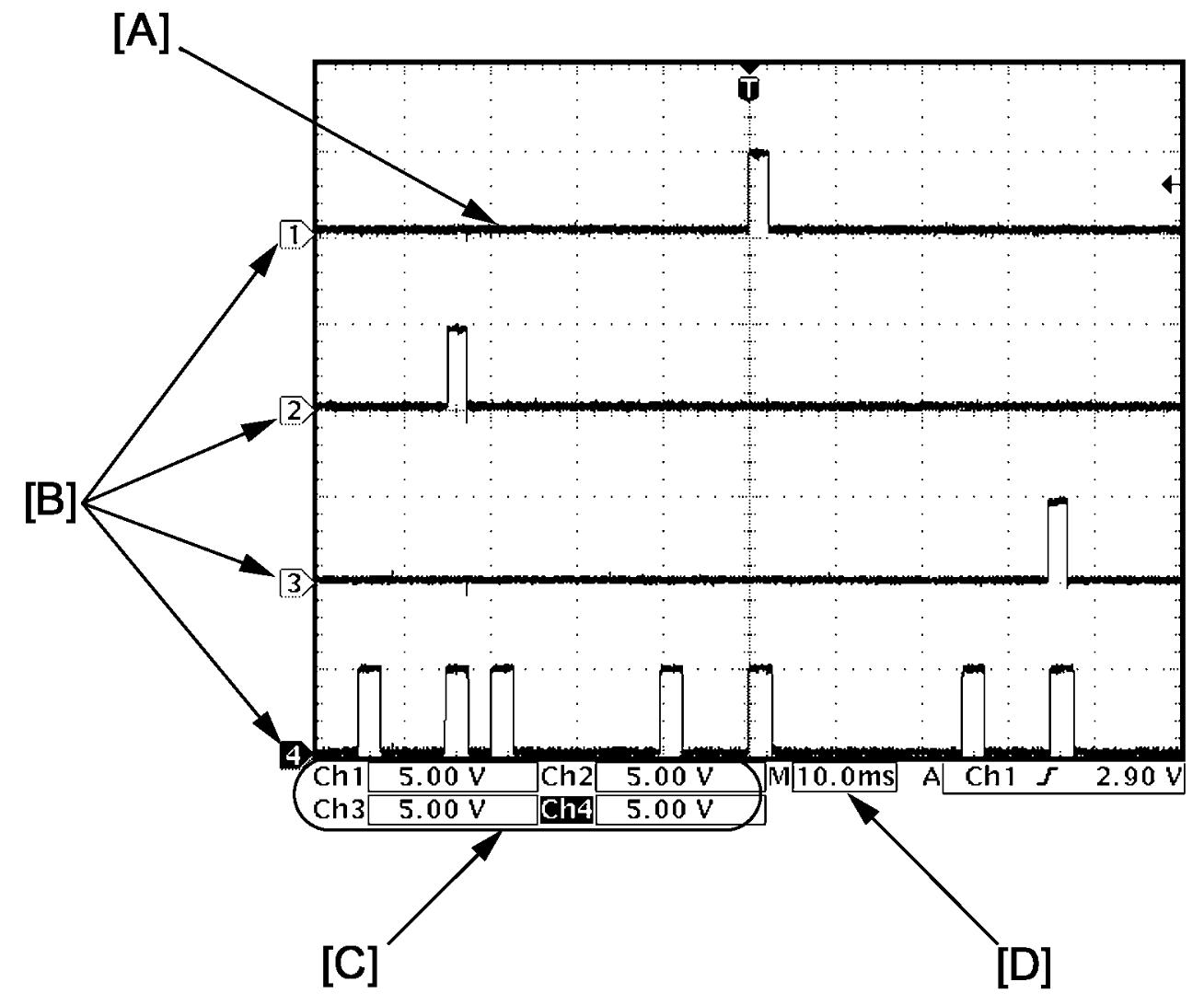

•Waveform varies depending on measurement condition and vehicle spec.
| [A]: | Waveform of channel 1 | [C]: | VOLT/DIV of each channel |
| [B]: | Ground level of each channel | [D]: | TIME/DIV |
Fuel injector signal
Fuel injector No.1 signal (high side) (1)
| Channel | Probe | Terminal No. |
|---|---|---|
| 1 | + | C01-33 |
| – | E01-6 |
Fuel injector No.1 signal (low side) (2)
| Channel | Probe | Terminal No. |
|---|---|---|
| 2 | + | C01-32 |
| – | E01-6 |
Fuel injector No.4 signal (high side) (3)
| Channel | Probe | Terminal No. |
|---|---|---|
| 3 | + | C01-48 |
| – | E01-6 |
Fuel injector No.4 signal (low side) (4)
| Channel | Probe | Terminal No. |
|---|---|---|
| 4 | + | C01-47 |
| – | E01-6 |
Fuel injector No.2 signal (high side) (1)
| Channel | Probe | Terminal No. |
|---|---|---|
| 1 | + | C01-16 |
| – | E01-6 |
Fuel injector No.2 signal (low side) (2)
| Channel | Probe | Terminal No. |
|---|---|---|
| 2 | + | C01-1 |
| – | E01-6 |
Fuel injector No.3 signal (high side) (3)
| Channel | Probe | Terminal No. |
|---|---|---|
| 3 | + | C01-31 |
| – | E01-6 |
Fuel injector No.3 signal (low side) (4)
| Channel | Probe | Terminal No. |
|---|---|---|
| 4 | + | C01-46 |
| – | E01-6 |
Measurement condition
•Engine: Idle speed after warming up
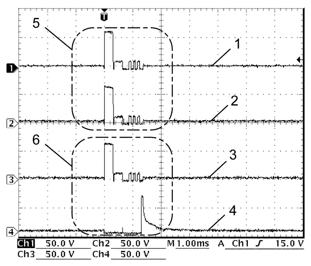
| 5. | Signal is outputted, but fuel is not injected. | 6. | Fuel is injected. |
Fuel injector No.1 signal and ignition coil No.1 signal
Fuel injector No.1 signal (low side) (1)
| Channel | Probe | Terminal No. |
|---|---|---|
| 1 | + | C01-32 |
| – | E01-6 |
Ignition coil No.1 signal (2)
| Channel | Probe | Terminal No. |
|---|---|---|
| 2 | + | C01-56 |
| – | E01-6 |
CMP sensor signal (3)
| Channel | Probe | Terminal No. |
|---|---|---|
| 3 | + | C01-20 |
| – | E01-6 |
CKP sensor signal (4)
| Channel | Probe | Terminal No. |
|---|---|---|
| 4 | + | C01-50 |
| – | E01-6 |
Measurement condition
•Engine: Idle speed after warming up
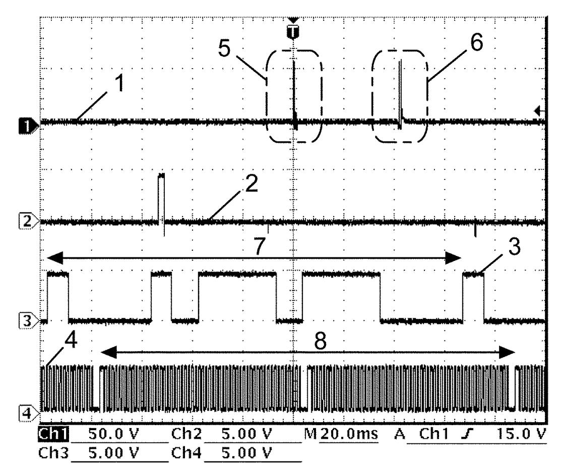
| 5. | Signal is outputted, but fuel is not injected. | 7. | Camshaft 360° angle |
| 6. | Fuel is injected. | 8. | Crankshaft 720° angle |
Fuel injector No.2 signal and ignition coil No.2 signal
Fuel injector No.2 signal (low side) (1)
| Channel | Probe | Terminal No. |
|---|---|---|
| 1 | + | C01-1 |
| – | E01-6 |
Ignition coil No.2 signal (2)
| Channel | Probe | Terminal No. |
|---|---|---|
| 2 | + | C01-41 |
| – | E01-6 |
CMP sensor signal (3)
| Channel | Probe | Terminal No. |
|---|---|---|
| 3 | + | C01-20 |
| – | E01-6 |
CKP sensor signal (4)
| Channel | Probe | Terminal No. |
|---|---|---|
| 4 | + | C01-50 |
| – | E01-6 |
Measurement condition
•Engine: Idle speed after warming up
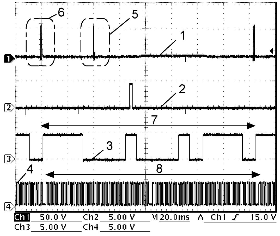
| 5. | Signal is outputted, but fuel is not injected. | 7. | Camshaft 360° angle |
| 6. | Fuel is injected. | 8. | Crankshaft 720° angle |
Fuel injector No.3 signal and ignition coil No.3 signal
Fuel injector No.3 signal (low side) (1)
| Channel | Probe | Terminal No. |
|---|---|---|
| 1 | + | C01-46 |
| – | E01-6 |
Ignition coil No.3 signal (2)
| Channel | Probe | Terminal No. |
|---|---|---|
| 2 | + | C01-42 |
| – | E01-6 |
CMP sensor signal (3)
| Channel | Probe | Terminal No. |
|---|---|---|
| 3 | + | C01-20 |
| – | E01-6 |
CKP sensor signal (4)
| Channel | Probe | Terminal No. |
|---|---|---|
| 4 | + | C01-50 |
| – | E01-6 |
Measurement condition
•Engine: Idle speed after warming up
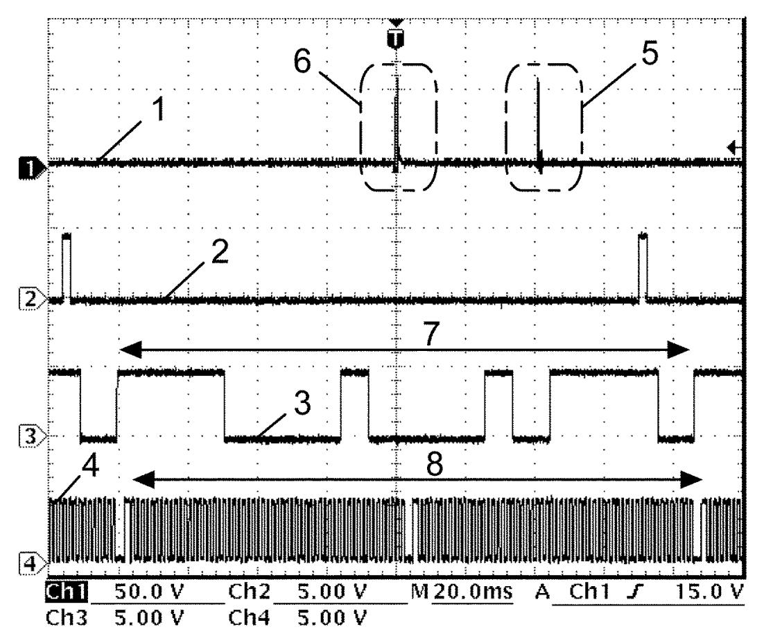
| 5. | Signal is outputted, but fuel is not injected. | 7. | Camshaft 360° angle |
| 6. | Fuel is injected. | 8. | Crankshaft 720° angle |
Fuel injector No.4 signal and ignition coil No.4 signal
Fuel injector No.4 signal (low side) (1)
| Channel | Probe | Terminal No. |
|---|---|---|
| 1 | + | C01-47 |
| – | E01-6 |
Ignition coil No.4 signal (2)
| Channel | Probe | Terminal No. |
|---|---|---|
| 2 | + | C01-57 |
| – | E01-6 |
CMP sensor signal (3)
| Channel | Probe | Terminal No. |
|---|---|---|
| 3 | + | C01-20 |
| – | E01-6 |
CKP sensor signal (4)
| Channel | Probe | Terminal No. |
|---|---|---|
| 4 | + | C01-50 |
| – | E01-6 |
Measurement condition
•Engine: Idle speed after warming up
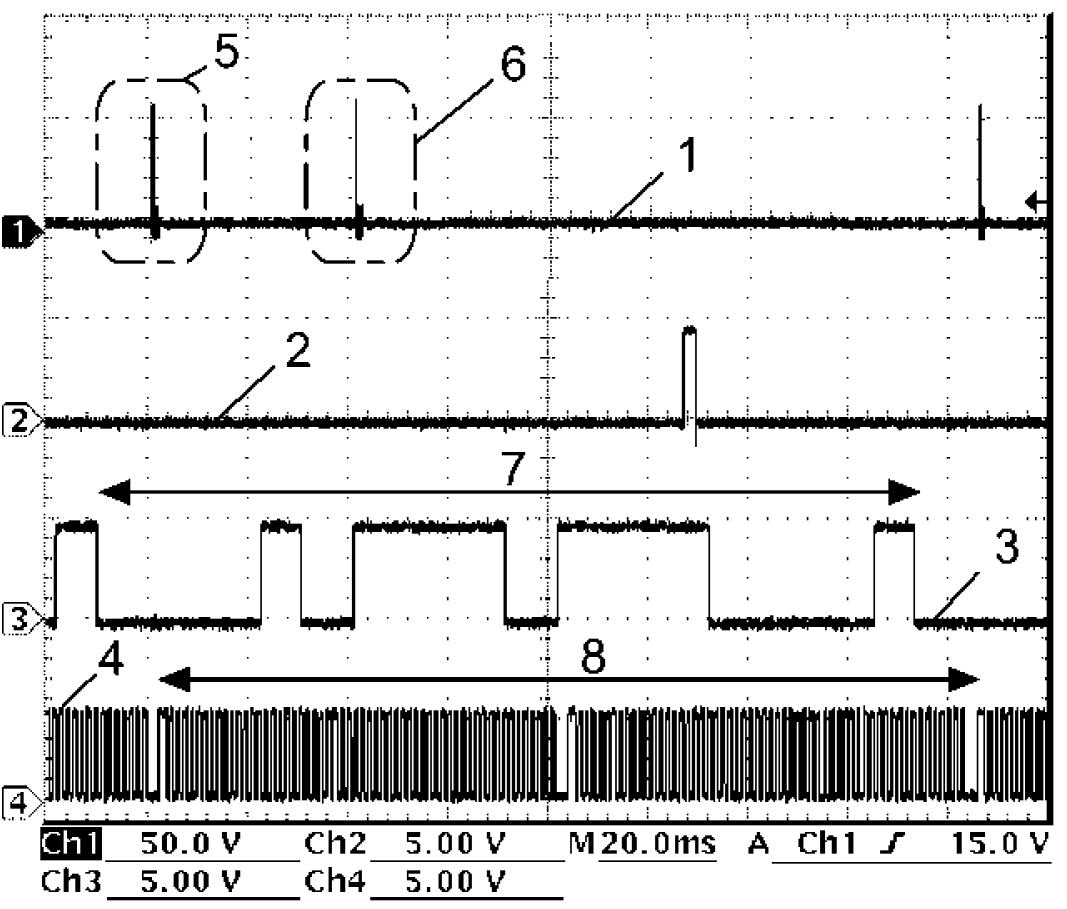
| 5. | Signal is outputted, but fuel is not injected. | 7. | Camshaft 360° angle |
| 6. | Fuel is injected. | 8. | Crankshaft 720° angle |
WGV-VSV signal
| Channel | Probe | Terminal No. |
|---|---|---|
| 1 | + | C01-2 |
| – | E01-6 |
Measurement condition
•WGV-VSV: 10% open (using active test of SUZUKI scan tool)
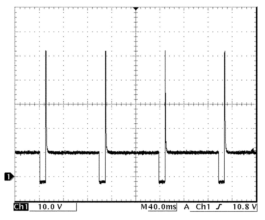
OCV signal
| Channel | Probe | Terminal No. |
|---|---|---|
| 1 | + | C01-3 |
| – | E01-6 |
Measurement condition
•Engine: Racing after warming up
•Accelerator pedal: Fully depressed position
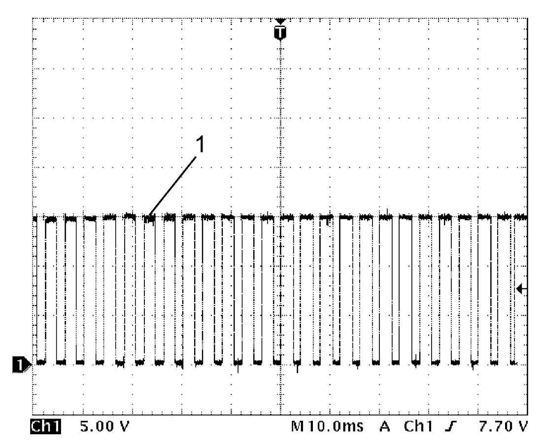
•Accelerator pedal: Fully depressed position
| 1. | OCV signal |
Throttle actuator signal
Throttle actuator signal (open) (1)
| Channel | Probe | Terminal No. |
|---|---|---|
| 1 | + | C01-4 |
| – | E01-6 |
Throttle actuator signal (close) (2)
| Channel | Probe | Terminal No. |
|---|---|---|
| 2 | + | C01-19 |
| – | E01-6 |
Measurement condition
•Engine: Idle speed after warming up
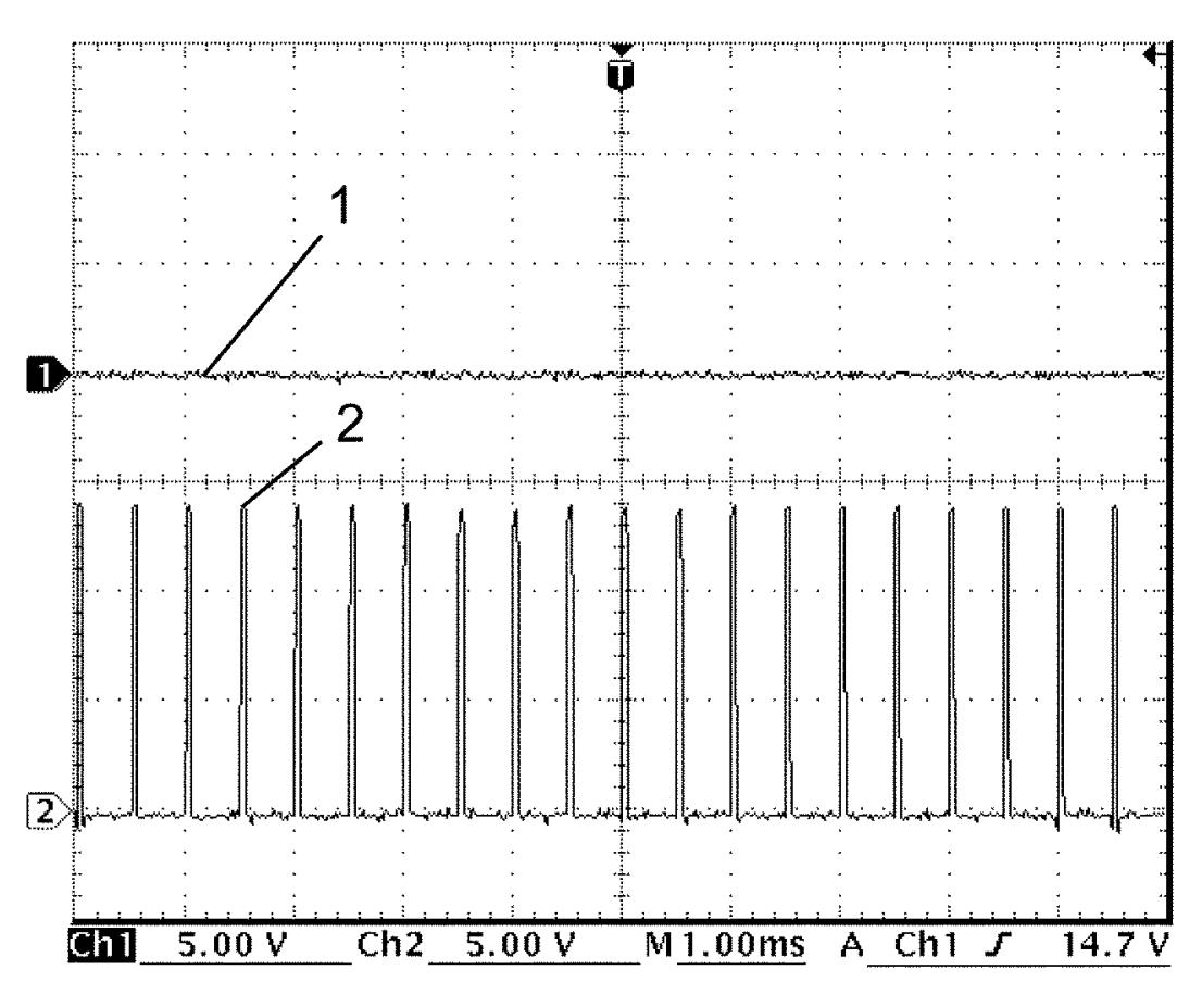
Measurement condition
•Engine: Racing at 3,000 rpm after warming up
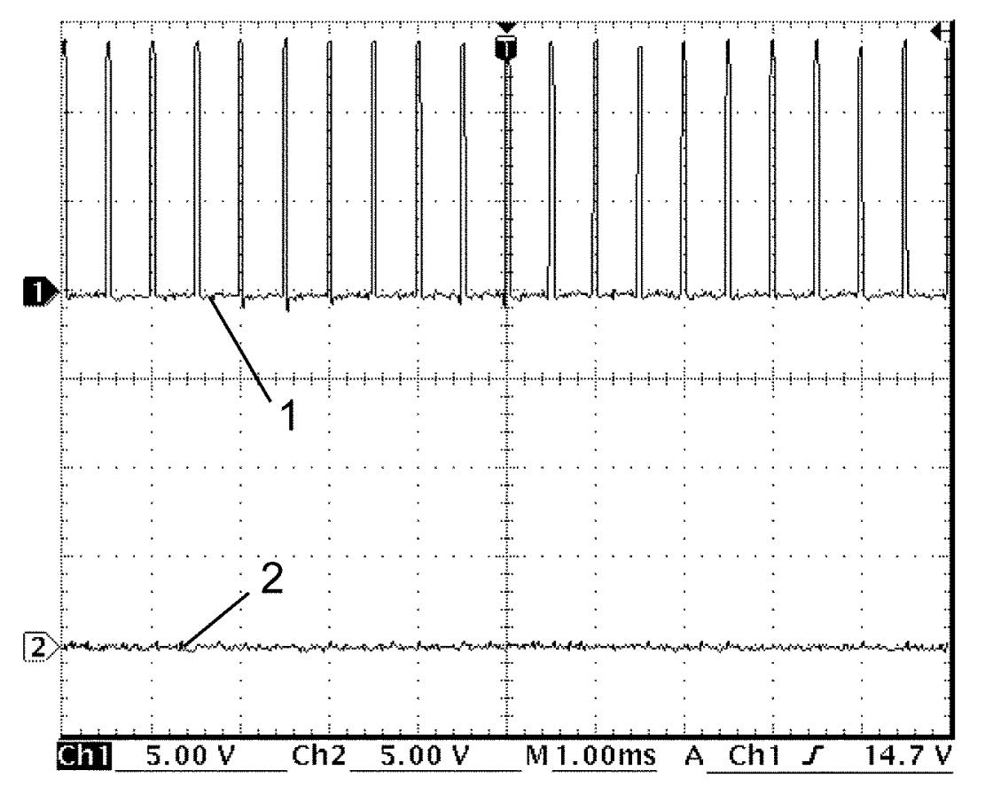
ABV-VSV signal
| Channel | Probe | Terminal No. |
|---|---|---|
| 1 | + | C01-5 |
| – | E01-6 |
Measurement condition
•ABV-VSV: OFF → ON → OFF (using active test of SUZUKI scan tool)
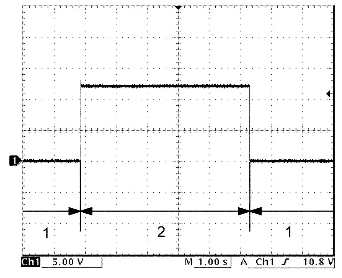
| 1. | OFF | 2. | ON |
HO2S-2 signal
| Channel | Probe | Terminal No. |
|---|---|---|
| 1 | + | C01-12 |
| – | E01-6 |
Measurement condition
•Engine: Racing after warming up
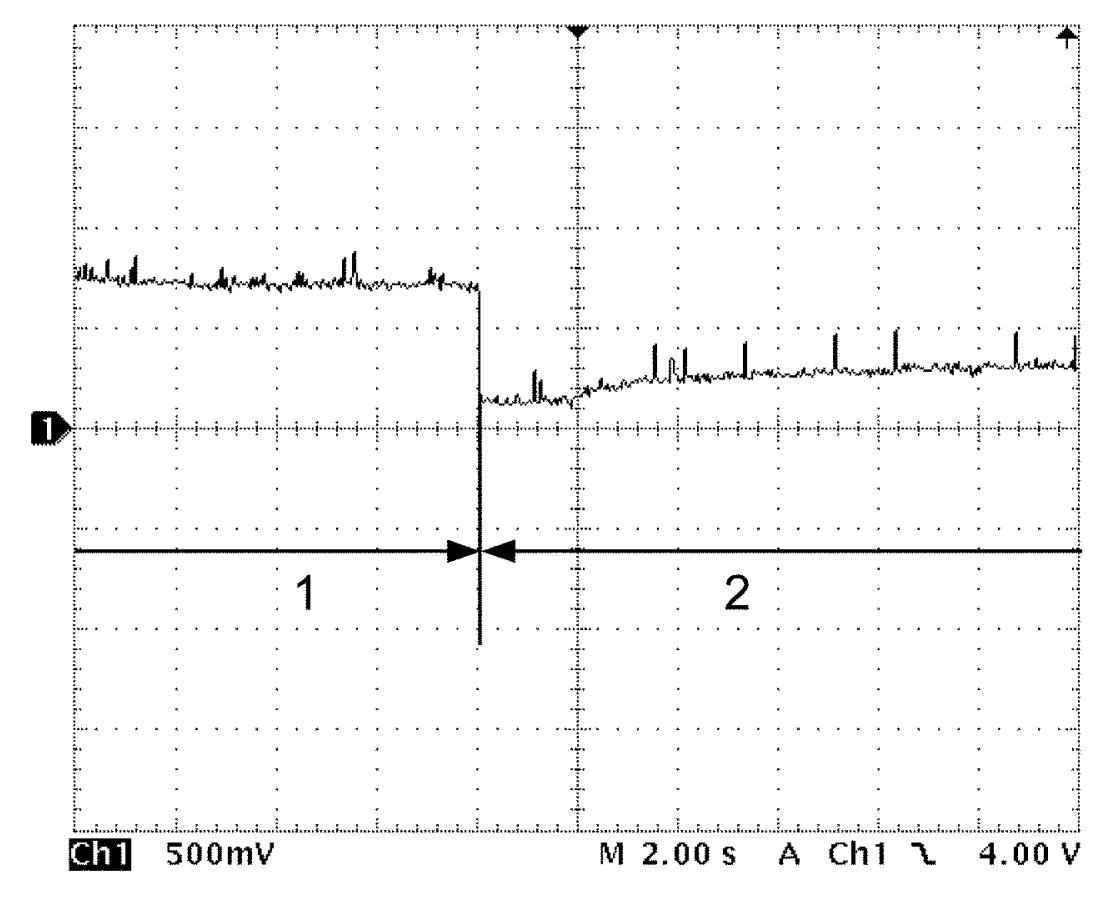
| 1. | Engine: Racing | 2. | Engine: Idle speed |
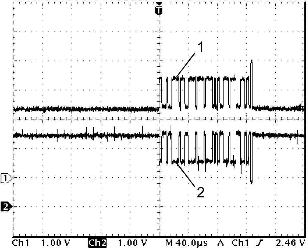
CAN communication signal
CAN (high) communication signal (1)
| Channel | Probe | Terminal No. |
|---|---|---|
| 1 | + | C01-29 E01-83 |
| – | E01-6 |
CAN (low) communication signal (2)
| Channel | Probe | Terminal No. |
|---|---|---|
| 2 | + | C01-14 E01-61 |
| – | E01-6 |
Measurement condition
•Ignition: “ON”
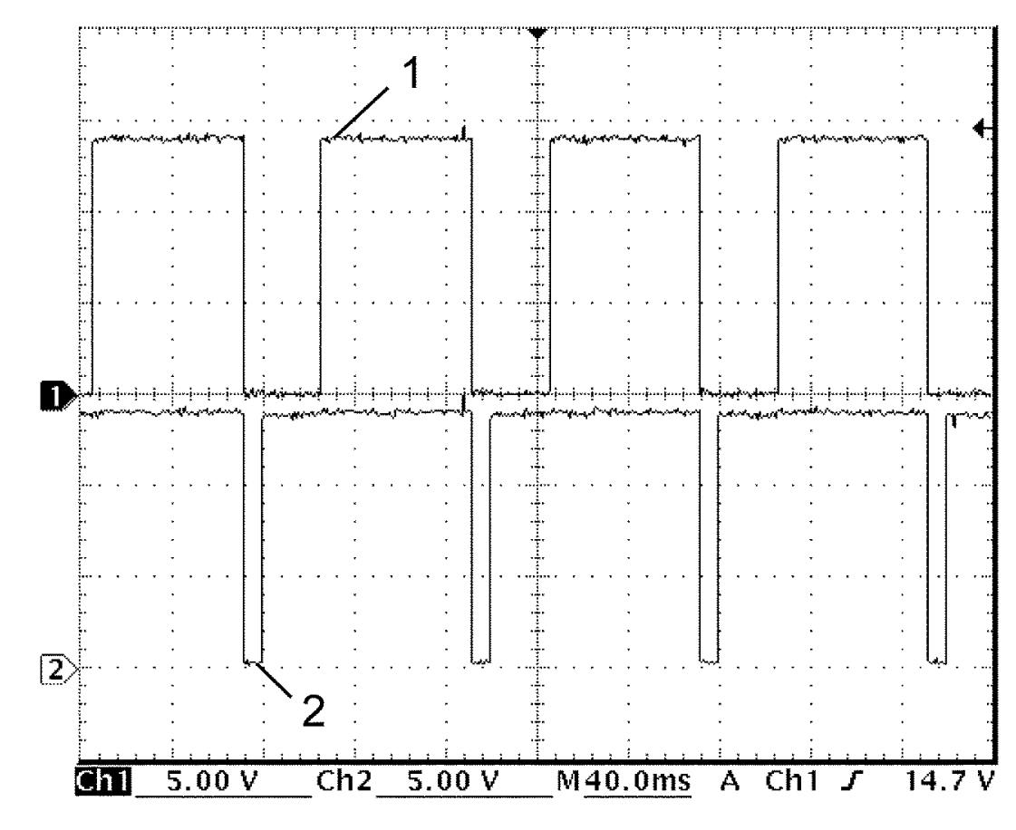
HO2S-1 heater signal and HO2S-2 heater signal
HO2S-1 heater signal (1)
| Channel | Probe | Terminal No. |
|---|---|---|
| 1 | + | C01-15 |
| – | E01-6 |
HO2S-2 heater signal (2)
| Channel | Probe | Terminal No. |
|---|---|---|
| 2 | + | C01-30 |
| – | E01-6 |
Measurement condition
•Engine: Idle speed after warming up
EVAP canister purge valve signal
| Channel | Probe | Terminal No. |
|---|---|---|
| 1 | + | C01-17 |
| – | E01-6 |
Measurement condition
•EVAP canister purge valve: 10% open (using active test of SUZUKI scan tool)
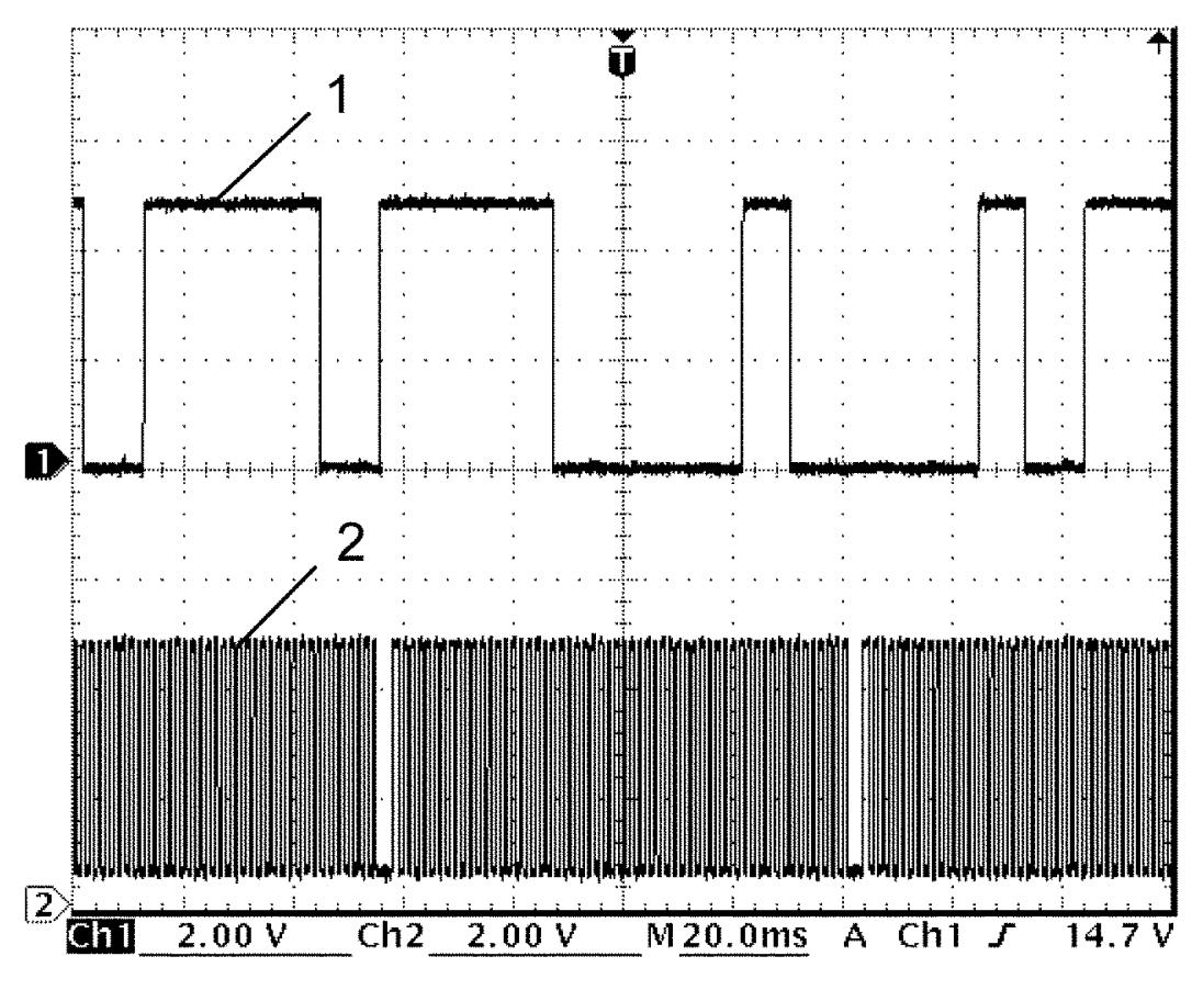
CMP sensor signal and CKP sensor signal
CMP sensor signal (1)
| Channel | Probe | Terminal No. |
|---|---|---|
| 1 | + | C01-20 |
| – | E01-6 |
CKP sensor signal (2)
| Channel | Probe | Terminal No. |
|---|---|---|
| 2 | + | C01-50 |
| – | E01-6 |
Measurement condition
•Engine: Idle speed after warming up
CKP sensor signal (Non-ENG A-STOP model)
| Channel | Probe | Terminal No. |
|---|---|---|
| 1 | + | C01-50 |
| – | E01-6 |
Measurement condition
•Engine: Idle speed after warming up
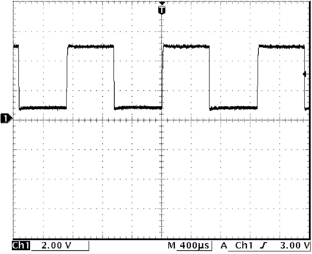
CKP sensor signal (ENG A-STOP model)
| Channel | Probe | Terminal No. |
|---|---|---|
| 1 | + | C01-50 |
| – | E01-6 |
Measurement condition
•Engine: Idle speed after warming up
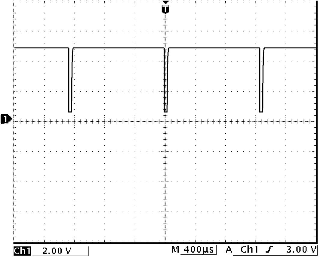
High pressure fuel pump signal
| Channel | Probe | Terminal No. |
|---|---|---|
| 1 | + | C01-34 |
| – | E01-6 |
Measurement condition
Engine: Idle speed after warming up
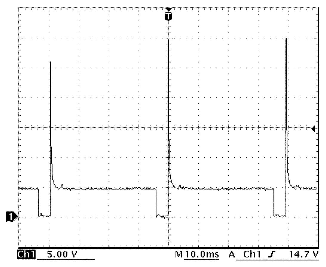
Knock sensor signal
| Channel | Probe | Terminal No. |
|---|---|---|
| 1 | + | C01-37 C01-52 |
| – | E01-6 |
Measurement condition
•Engine: Racing at 3,000 rpm after warming up
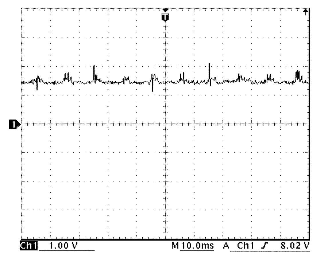
MAF sensor signal, boost pressure sensor signal and MAP sensor signal
MAF sensor signal (1)
| Channel | Probe | Terminal No. |
|---|---|---|
| 1 | + | C01-45 |
| – | E01-6 |
Boost pressure sensor signal (2)
| Channel | Probe | Terminal No. |
|---|---|---|
| 2 | + | C01-39 |
| – | E01-6 |
MAP sensor signal (3)
| Channel | Probe | Terminal No. |
|---|---|---|
| 3 | + | C01-40 |
| – | E01-6 |
Measurement condition
•Engine: Racing after warming up
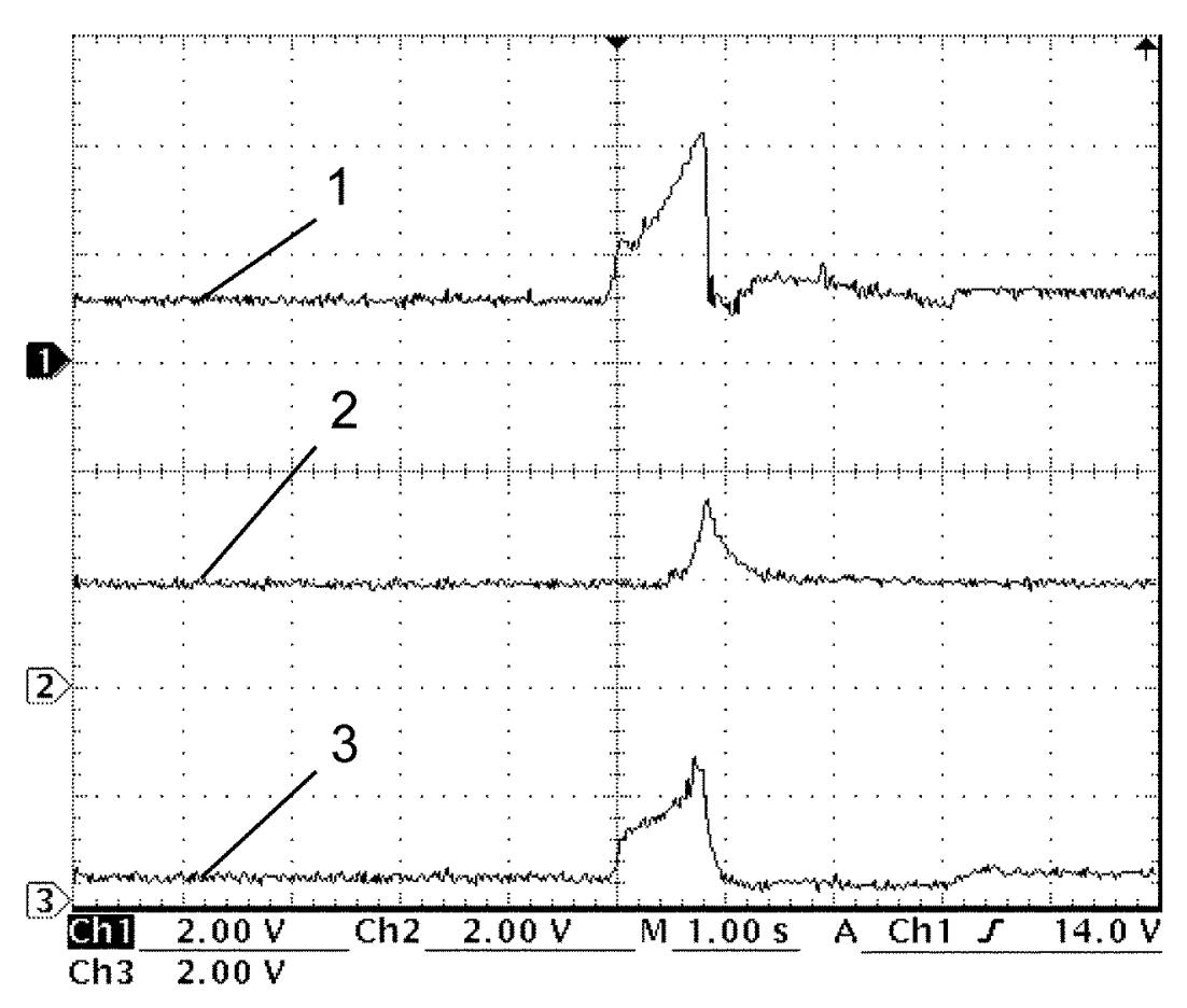
Ignition coil signal
| Channel | Probe | Terminal No. |
|---|---|---|
| 1 | + | C01-56 (No.1) C01-41 (No.2) C01-42 (No.3) C01-57 (No.4) |
| – | E01-6 |
Measurement condition
•Engine: Idle speed after warming up
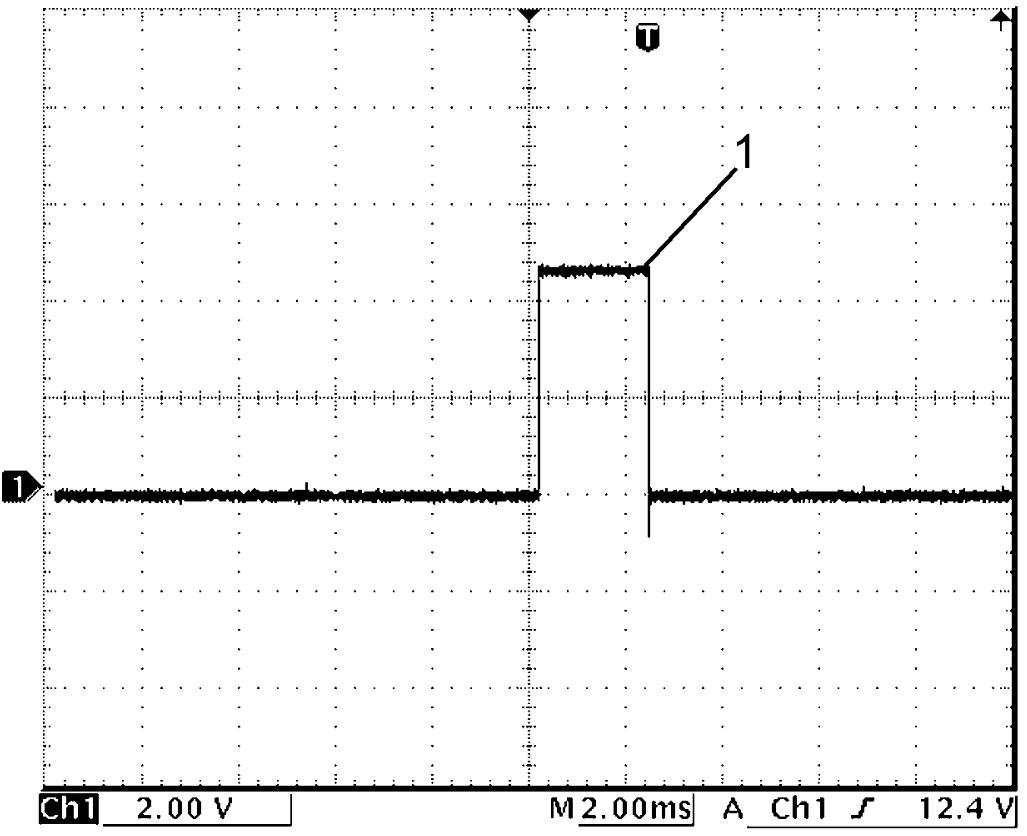
| 1. | Ignition coil signal |
HO2S-1 signal
| Channel | Probe | Terminal No. |
|---|---|---|
| 1 | + | C01-73 |
| – | E01-6 |
Measurement condition
•Engine: Idle speed after warming up
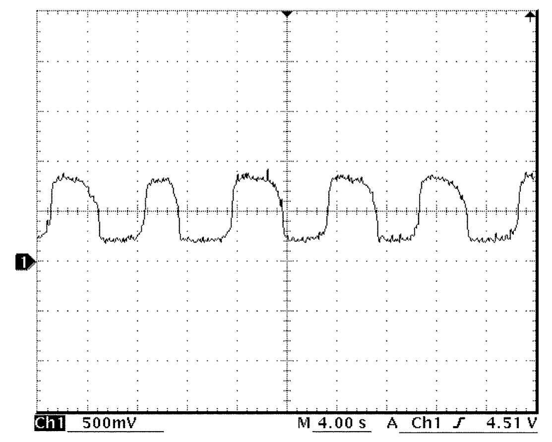
Generator LIN communication signal
| Channel | Probe | Terminal No. |
|---|---|---|
| 1 | + | C01-60 |
| – | E01-6 |
Measurement condition
•Ignition: “ON”
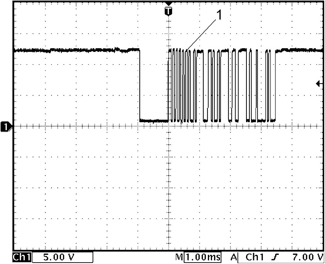
| 1. | LIN communication signal |
Fuel pump relay signal
| Channel | Probe | Terminal No. |
|---|---|---|
| 1 | + | E01-70 |
| – | E01-6 |
Measurement condition
•Ignition: “OFF” → “ON” → “START”
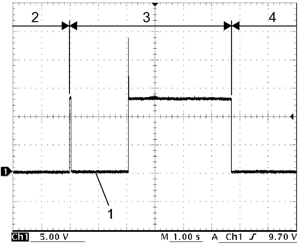
| 1. | Fuel pump relay signal | 3. | Ignition: “ON” |
| 2. | Ignition: “OFF” | 4. | Ignition: “START” |