Fuel Injector Circuit Check
Precautions: General safety (00)
NOTE:
•This procedure is to troubleshoot only open, short to ground circuit and short to power supply circuit of fuel injector circuit. If it is necessary to troubleshoot for injector operation, perform High-Pressure Fuel Supply Circuit Check:D16AA.
•For identification of each cylinder, refer to Statement on Cleanliness and Care:D16AA.
•For identification of each cylinder, refer to Statement on Cleanliness and Care:D16AA.
Circuit Diagram
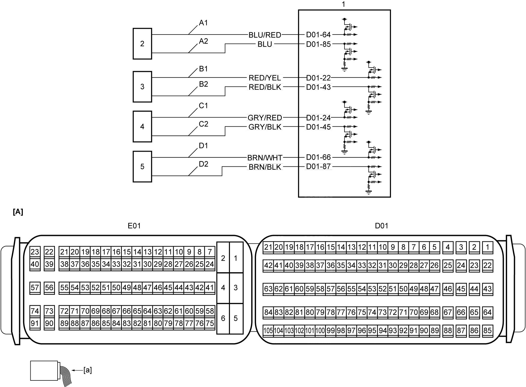
| [A]: | ECM connector (View: [a]) | C1: | Fuel injector No.3 drive circuit (high side) | 2. | Fuel injector No.1 |
| A1: | Fuel injector No.1 drive circuit (high side) | C2: | Fuel injector No.3 drive circuit (low side) | 3. | Fuel injector No.2 |
| A2: | Fuel injector No.1 drive circuit (low side) | D1: | Fuel injector No.4 drive circuit (high side) | 4. | Fuel injector No.3 |
| B1: | Fuel injector No.2 drive circuit (high side) | D2: | Fuel injector No.4 drive circuit (low side) | 5. | Fuel injector No.4 |
| B2: | Fuel injector No.2 drive circuit (low side) | 1. | ECM |
Troubleshooting
| Step | Action | Yes | No |
|---|---|---|---|
| 1 |
Fuel injector drive circuit (high side) and (low side) check
1)When ignition is “OFF”, disconnect “D01” connector from ECM and all fuel injector connectors.
2)Check for proper terminal connection to “D01” connector and all fuel injector connectors.
3)If connections are OK, check the following points.
•Resistance of “A1”, “A2”, “B1”, “B2”, “C1”, “C2”, “D1” and “D2” circuits: less than 1 Ω
•Resistance between each of “A1”, “A2”, “B1”, “B2”, “C1”, “C2”, “D1” and “D2” circuits and ground: infinity •Resistance between “A1” circuit terminal and other terminal at fuel injector connector: infinity •Resistance between “B1” circuit terminal and other terminal at fuel injector connector: infinity •Resistance between “C1” circuit terminal and other terminal at fuel injector connector: infinity •Resistance between “D1” circuit terminal and other terminal at fuel injector connector: infinity •Voltage of “A1”, “A2”, “B1”, “B2”, “C1”, “C2”, “D1” and “D2” circuits: approx. 0 V (When ignition is “ON”) Is check result OK?
|
Go to Step 2.
|
Repair defective circuit.
|
| 2 |
Fuel injector check
1)Check fuel injector.

Is check result OK?
|
End.
|
Replace fuel injector.
|