Turbocharger Removal and Installation
Precautions: General safety (00)
 CAUTION:
Touching a hot exhaust system component will cause a burn.
Do not perform any service work on the exhaust system until the exhaust system is cool.
NOTICE:
The turbocharger will lose its original performance if it is disassembled.
Do not disassemble the turbocharger.
If any faulty condition is found, replace the turbocharger with a new one.
Removal
1)Drain coolant. 
2)Remove catalytic converter.
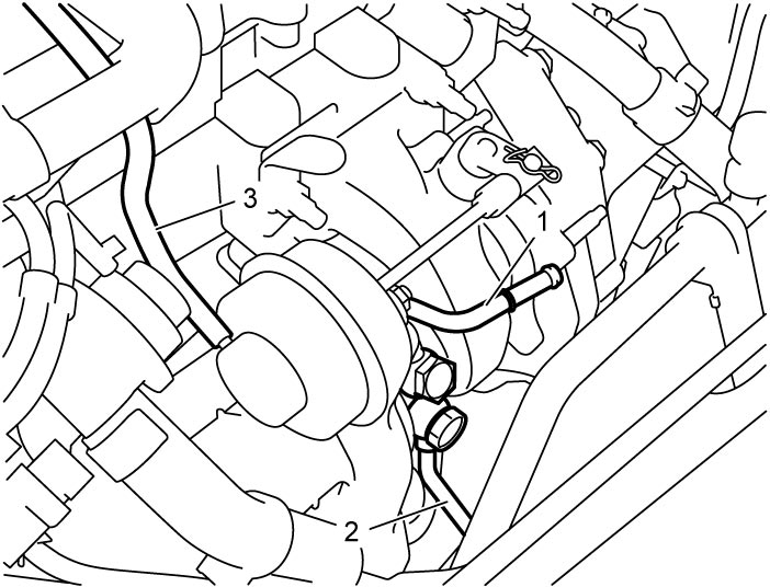
3)Remove turbocharger water inlet pipe (1) and turbocharger water outlet pipe (2).
4)Disconnect waste gate control hose No.1 (3).

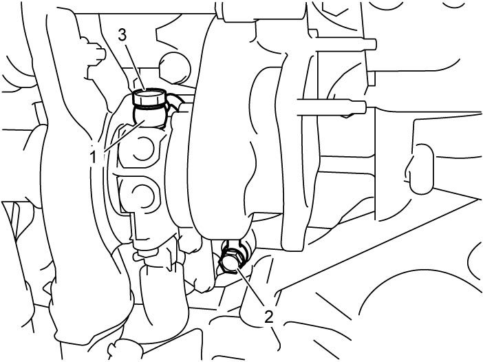
5)Remove turbocharger oil intake pipe (1) with oil intake pipe union bolt No.1 (2) and No.2 (3) and gaskets.
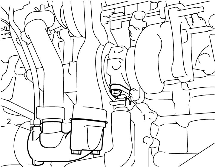
6)Remove oil drain joint (1).
7)Remove turbocharger outlet air pipe (2).
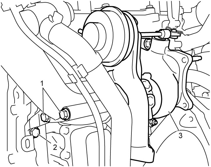
8)Remove turbocharger inlet air pipe bolts (1) and turbocharger inlet air pipe bracket bolt (2).
9)Remove turbocharger (3).
Installation
Reverse removal procedure noting the following points.
1)Install turbocharger (1) with new gasket, and then tighten turbocharger bolts (2) and nuts (3) to specified torque.
Turbocharger nut (b): 55 N·m (5.6 kgf-m, 40.5 lbf-ft)
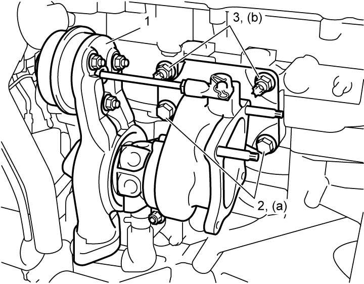
Tightening torque
Turbocharger bolt (a): 55 N·m (5.6 kgf-m, 40.5 lbf-ft)Turbocharger nut (b): 55 N·m (5.6 kgf-m, 40.5 lbf-ft)
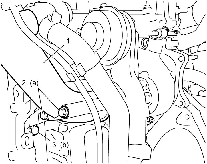
2)Install turbocharger inlet air pipe (1) as follows.
a)Install turbocharger inlet air pipe with new gasket to turbocharger.
b)Tighten turbocharger inlet air pipe bolts (2) and turbocharger inlet air pipe bracket bolt (3) by hand.
c)Tighten turbocharger inlet air pipe bolts to specified torque.
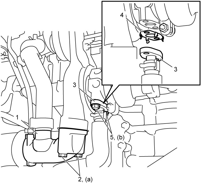
3)Install turbocharger outlet air pipe (1) with new gasket and tighten turbocharger outlet air pipe bolts (2) to specified torque.
4)Install oil drain joint (3) with new gasket (4) as follows.
a)Fit claws on gasket to oil drain joint flange.
5)Check mesh filter in oil intake pipe union bolt No.1 for cleanliness.
6)Install turbocharger oil intake pipe (1) with new gaskets, and then tighten turbocharger oil intake pipe union bolt No.1 (2) and No.2 (3) to specified torque.
Turbocharger oil intake pipe union bolt No.2 (b): 18 N·m (1.8 kgf-m, 13.5 lbf-ft)
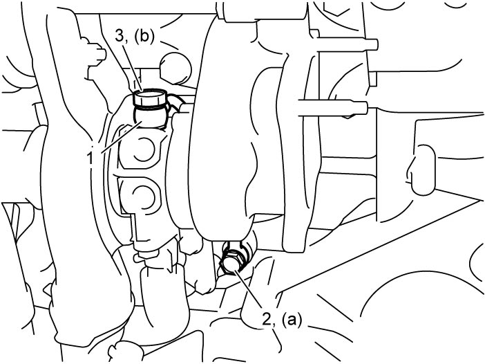
Tightening torque
Turbocharger oil intake pipe union bolt No.1 (a): 18 N·m (1.8 kgf-m, 13.5 lbf-ft)Turbocharger oil intake pipe union bolt No.2 (b): 18 N·m (1.8 kgf-m, 13.5 lbf-ft)
7)Connect waste gate control hose No.1 (1) to turbocharger.
8)Install turbocharger water inlet pipe (2) with new gaskets, and then tighten turbocharger water inlet pipe union bolt (3) to specified torque.
9)Install turbocharger water outlet pipe (4) with new gaskets, and then tighten turbocharger water outlet pipe union bolt (5) to specified torque.
Turbocharger water outlet pipe union bolt (b): 23 N·m (2.3 kgf-m, 17.0 lbf-ft)
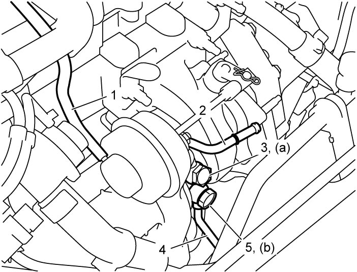
Tightening torque
Turbocharger water inlet pipe union bolt (a): 23 N·m (2.3 kgf-m, 17.0 lbf-ft)Turbocharger water outlet pipe union bolt (b): 23 N·m (2.3 kgf-m, 17.0 lbf-ft)
10)Install catalytic converter.
11)Refill cooling system with coolant.
12)Check cooling system for leakage.