Timing Belt, Belt Tensioner and Idler Pulley Removal and Installation
Precautions: General safety (00)
NOTICE:
•Turning high pressure pump pulley counterclockwise may cause damage to the pump.
Never turn high pressure pump pulley counterclockwise.
•After timing belt is removed, if crankshaft or camshaft is turned independently, piston and valves may interfere and hit with each other and be damaged.
Avoid turning each of the camshaft or crankshaft alone while timing belt is removed.
•Bend or twist timing belt and contact of oil or water, etc. to timing belt may adversely affect the belt life.
Do not bend or twist timing belt and do not allow contact of oil or water, etc. to timing belt.
Never turn high pressure pump pulley counterclockwise.
•After timing belt is removed, if crankshaft or camshaft is turned independently, piston and valves may interfere and hit with each other and be damaged.
Avoid turning each of the camshaft or crankshaft alone while timing belt is removed.
•Bend or twist timing belt and contact of oil or water, etc. to timing belt may adversely affect the belt life.
Do not bend or twist timing belt and do not allow contact of oil or water, etc. to timing belt.
Removal
1)Remove engine assembly. 
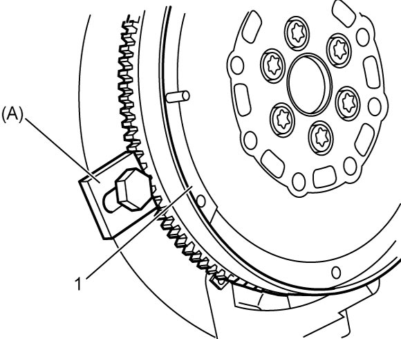
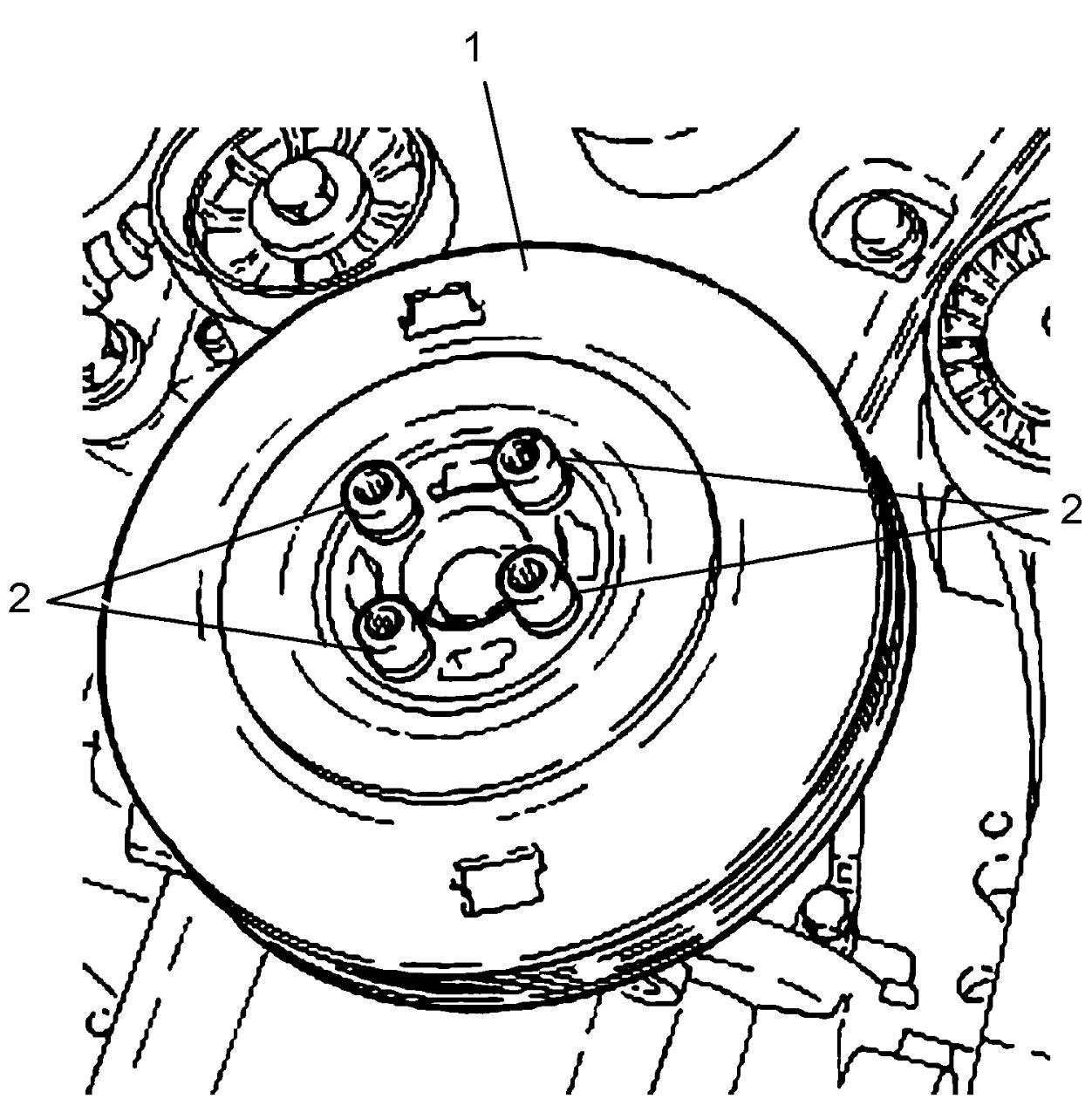
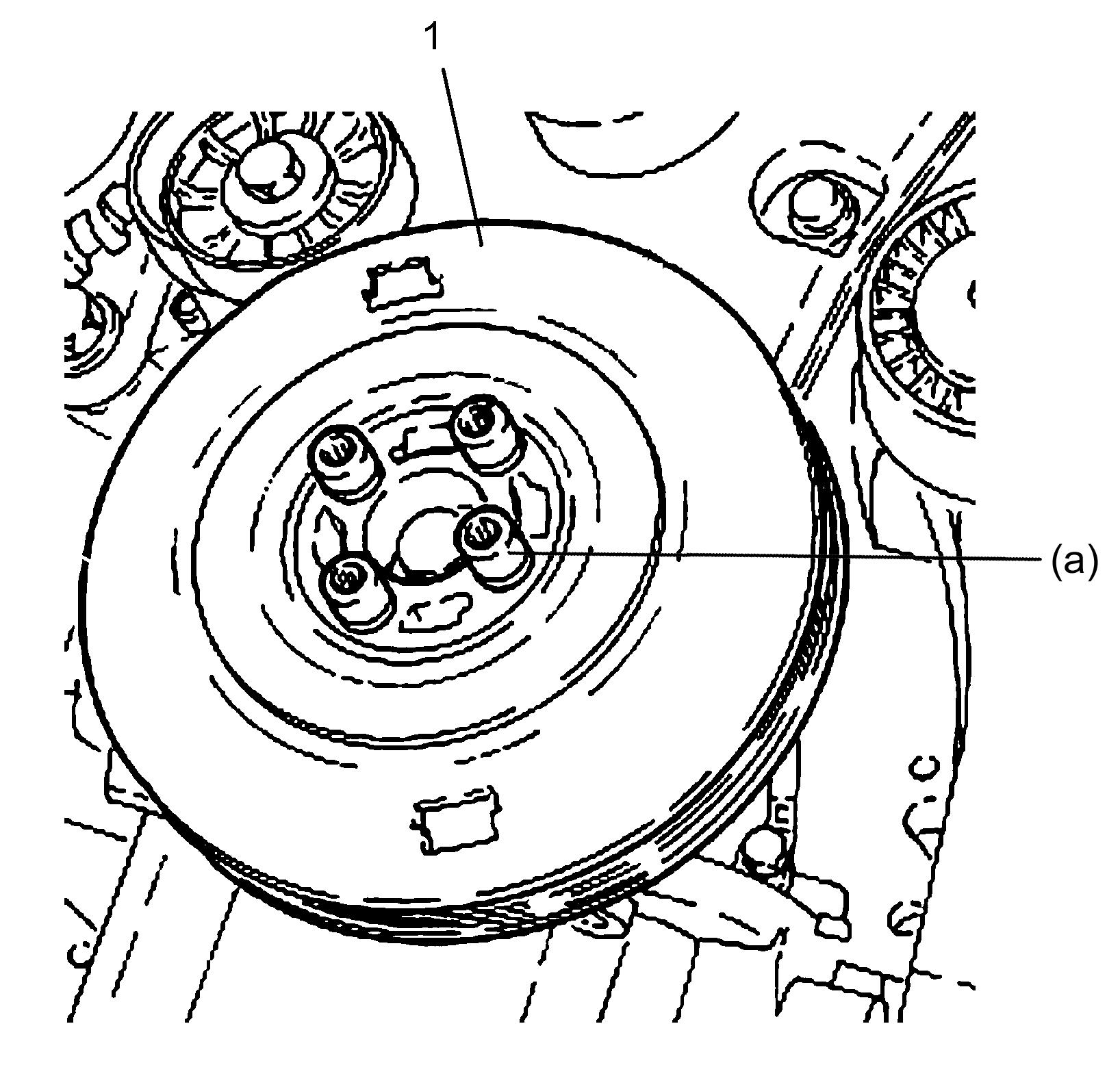
3)Remove bolts (2) and remove crankshaft pulley (1).

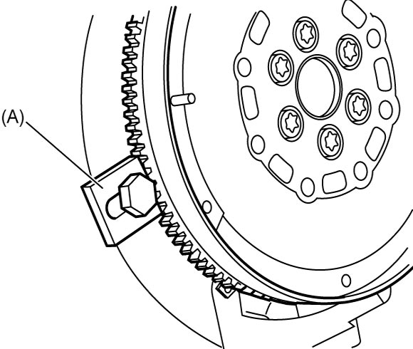
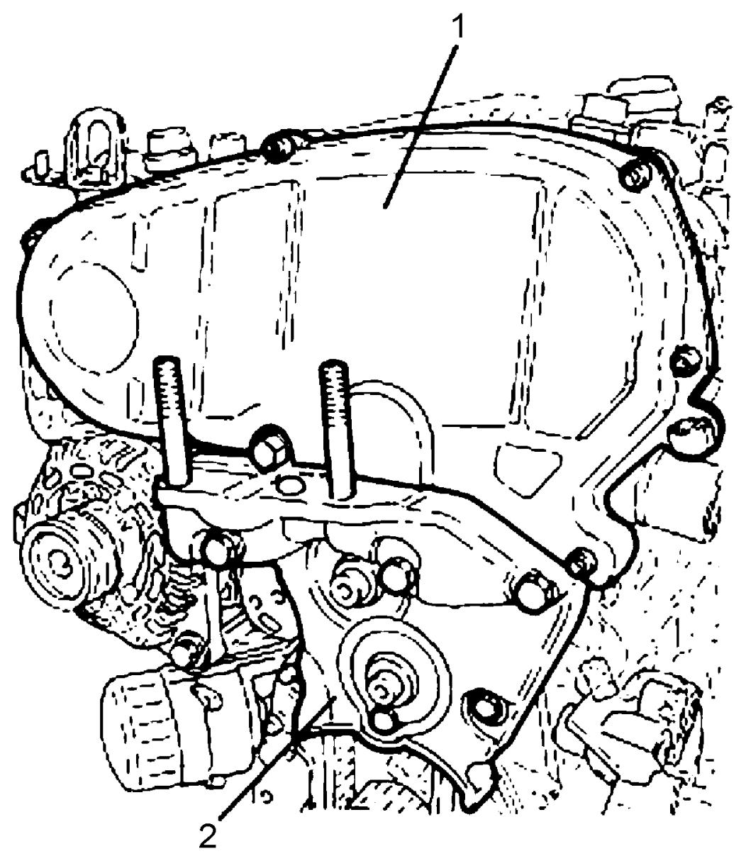
5)Remove timing belt cover (1).
6)Remove engine right mounting bracket (2).
7)Remove EGR-2 valve bracket.
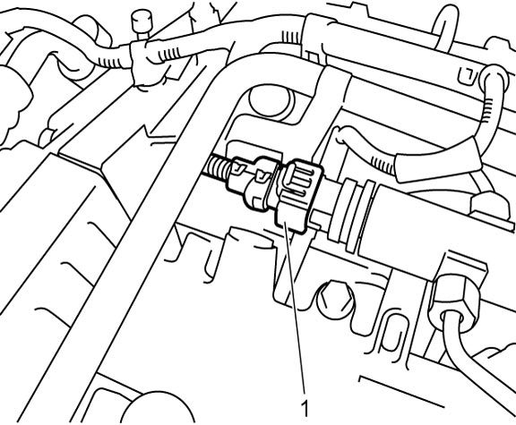
8)Disconnect connector (1) from fuel pressure sensor.
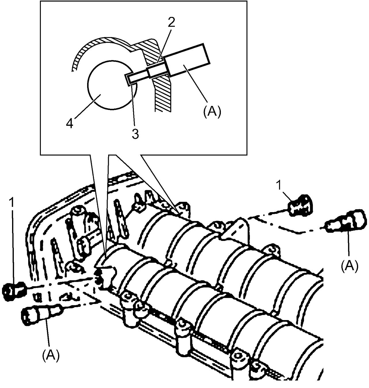
9)Remove camshaft housing plugs (1).
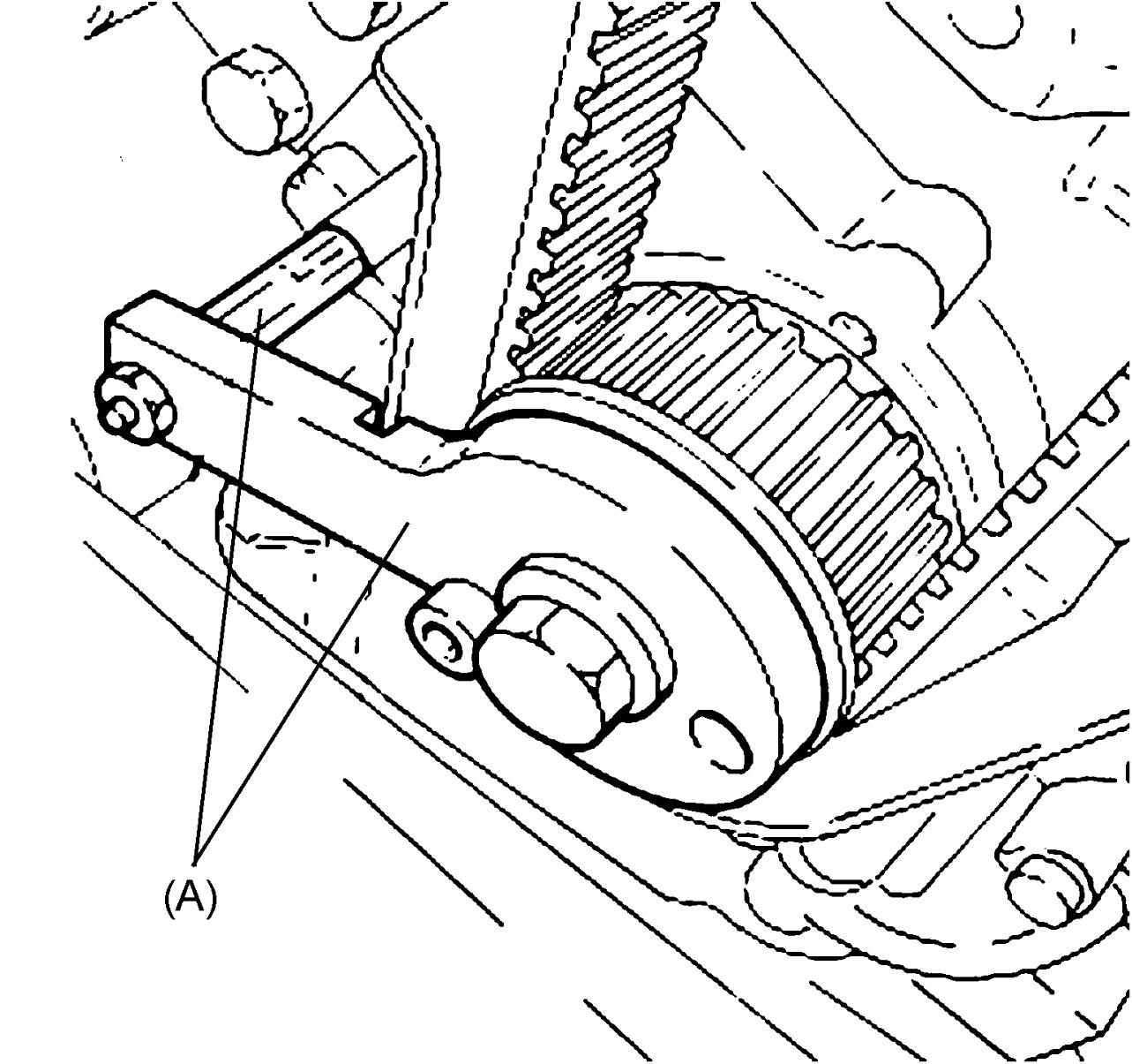
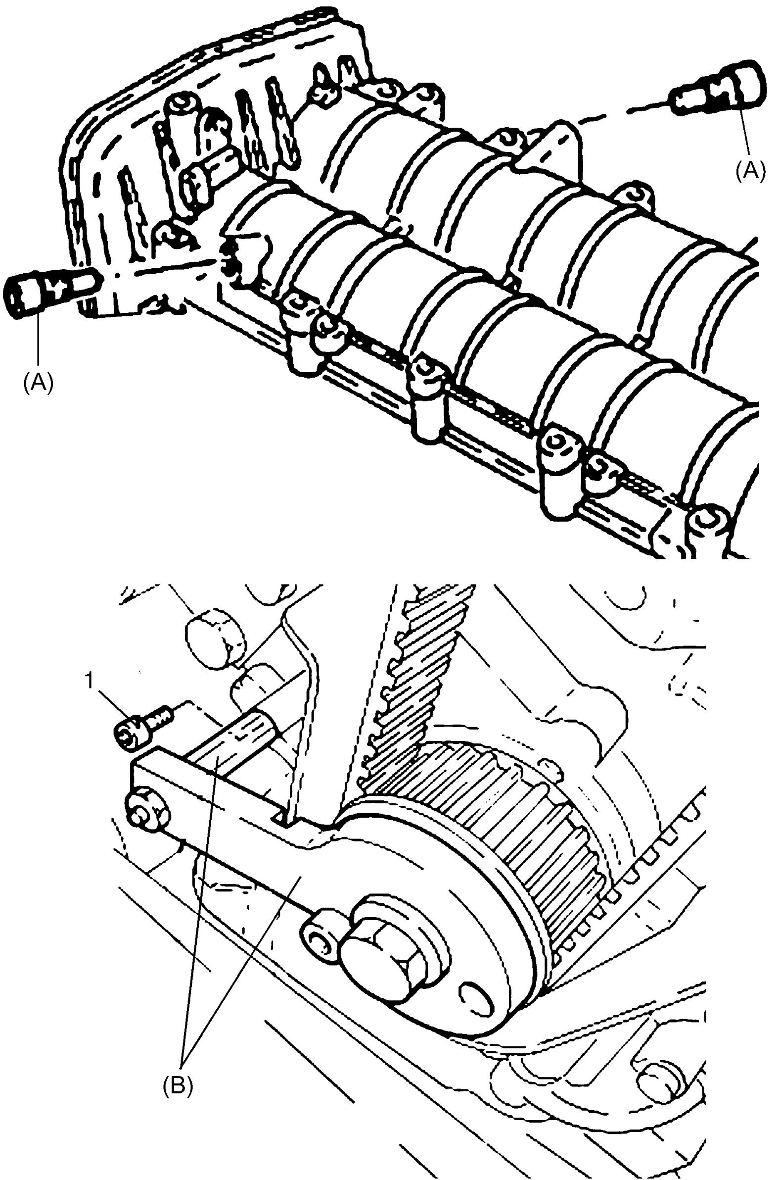
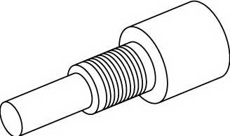
10)Turning crankshaft clockwise, align camshaft housing plug holes (2) with camshaft gaps (3) and lock camshafts (4) inserting special tools (A) to plug holes as shown in figure.
NOTE:
For correct installation of timing belt, keep special tools inserted until timing belt is installed.
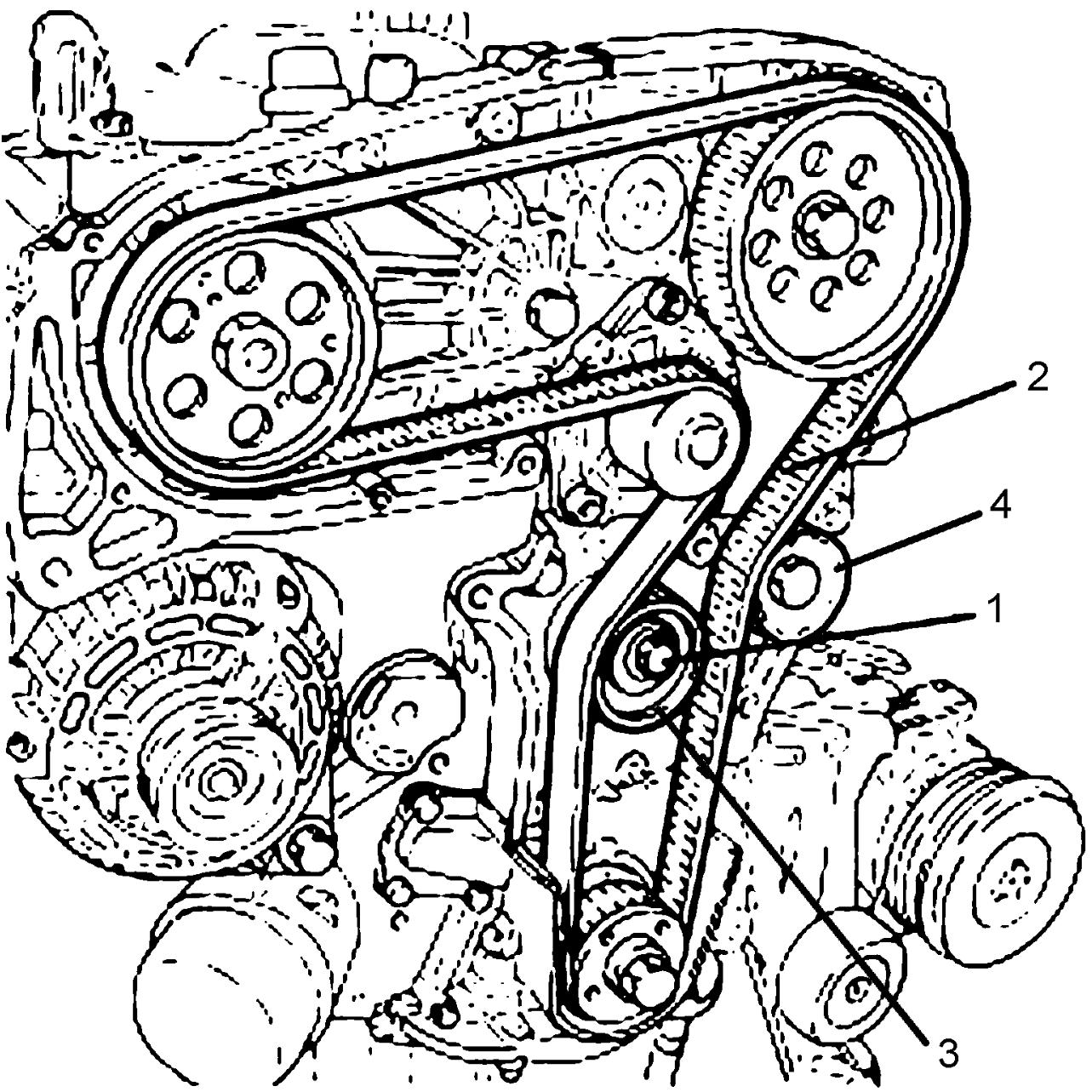
11)Loosen timing belt tensioner bolt (1) and remove timing belt (2).
12)Remove timing belt tensioner (3) and idler pulley (4).
Installation
1)Align crankshaft timing belt pulley as follows.
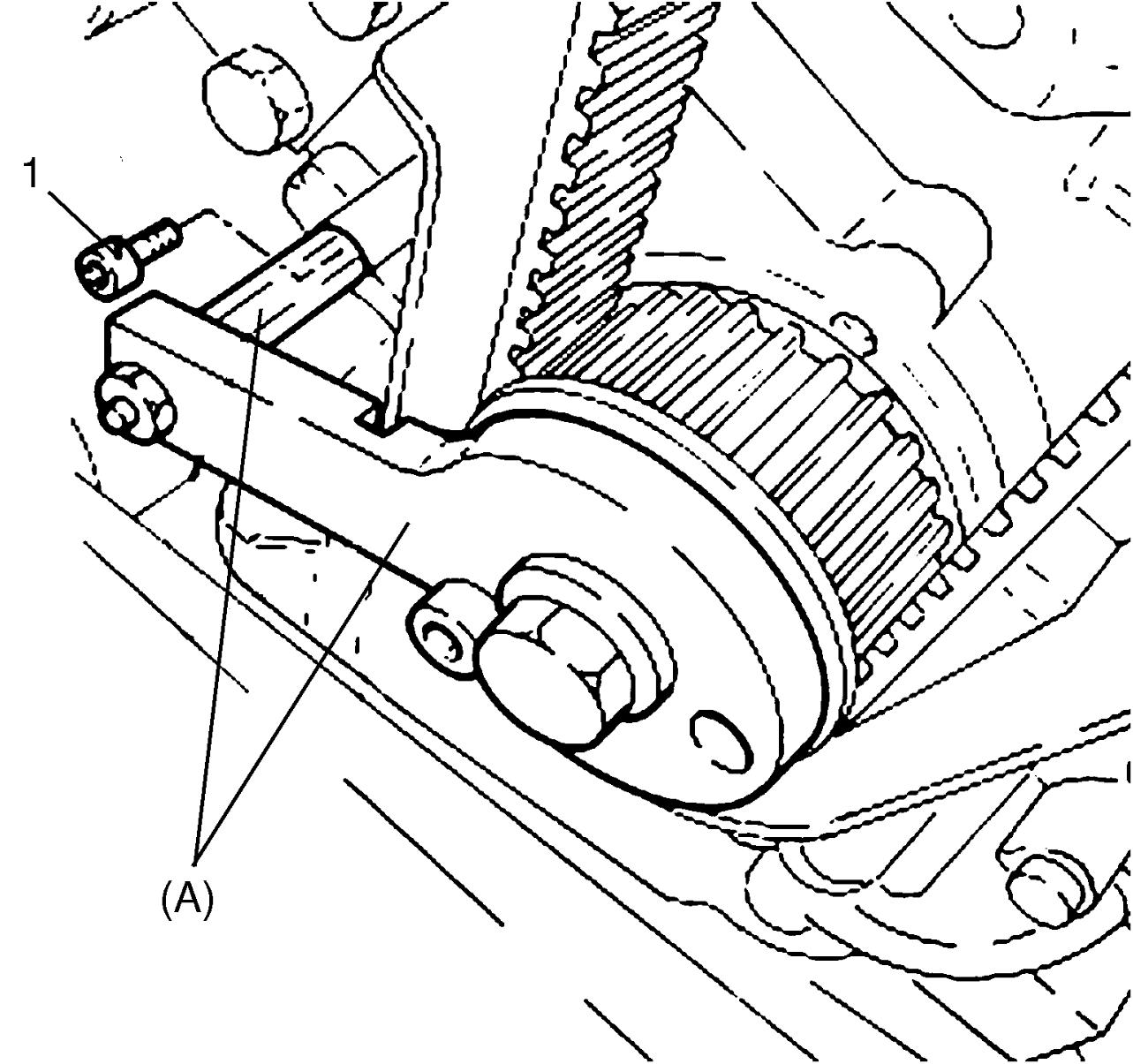
a)Remove oil pump bolt (1).
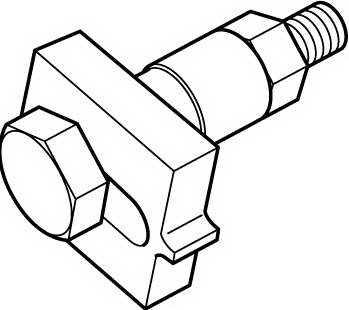
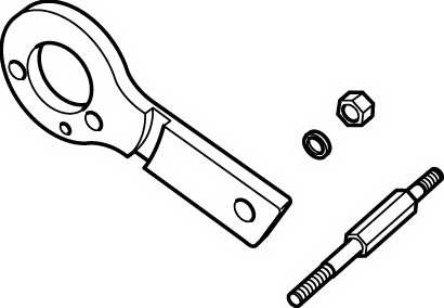
b)Install special tool to crankshaft timing belt pulley.
c)Rotate crankshaft slowly to fit locating dowel on crankshaft timing belt pulley into a hole in the tool.
d)Remove special tool from crankshaft timing belt pulley.
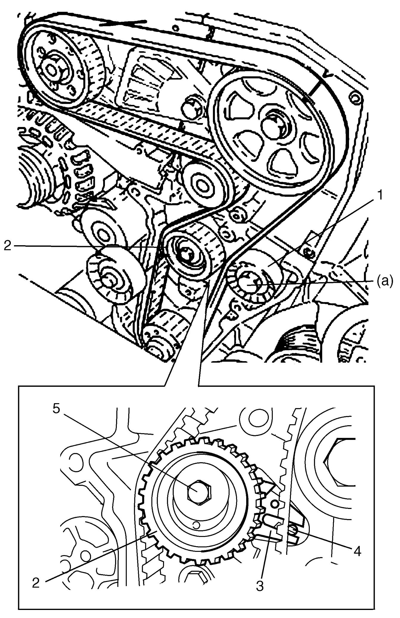
2)Install timing belt idler pulley (1).
3)Install timing belt tensioner (2) as follows.
a)Fit slit (3) of timing belt tensioner to protrusion (4) on timing belt tensioner support.
b)Tighten timing belt tensioner bolt (5) by hand.
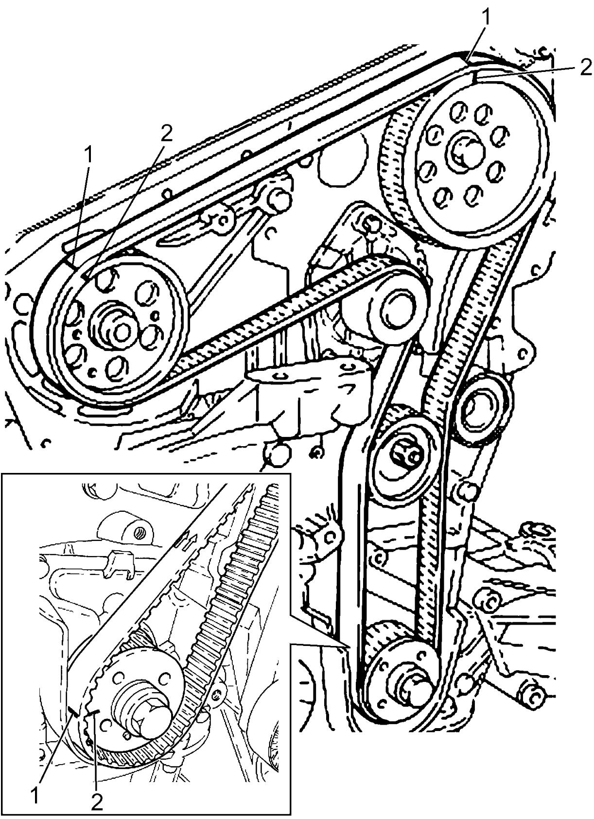
4)Install timing belt aligning matchmarks (1) on timing belt with matchmarks (2) on high pressure pump pulley, crankshaft timing belt pulley and camshaft timing pulley.
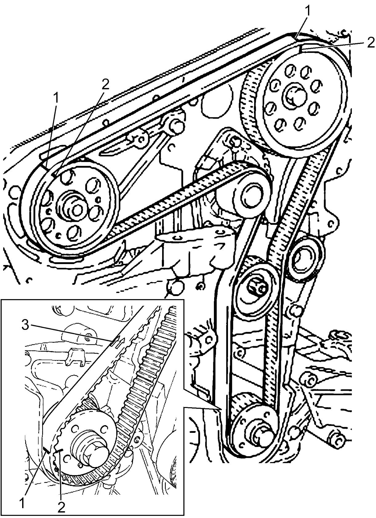
NOTE:
Set timing belt directing arrow mark (3) on the belt clockwise as shown in figure.
5)Install special tool to crankshaft timing belt pulley, rotate crankshaft slowly and fit locating dowel on crankshaft timing belt pulley into a hole in the tool.
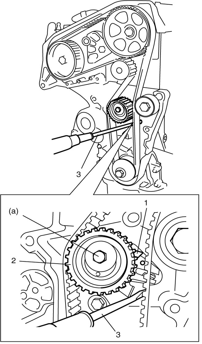
6)Using a flat-bladed screwdriver (3), align movable index (1) of timing belt tensioner (2) to maximum tension position as shown in figure. And then, tighten timing belt tensioner bolt to specified torque.
7)Check matchmarks (1) on timing belt to matchmarks (2) on high pressure pump pulley, crankshaft timing belt pulley and camshaft pulley.
9)Turn crankshaft two revolutions clockwise.
10)Adjust timing belt tension as follows.
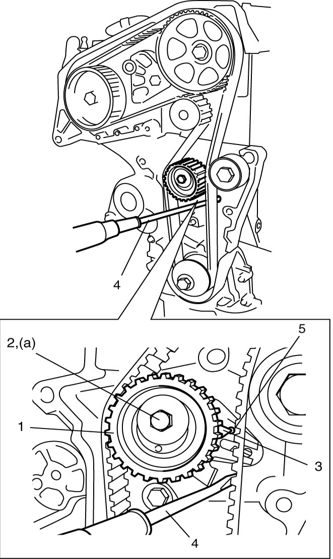
a)While keeping tension of timing belt using a flat-bladed screwdriver (4), loosen timing belt tensioner bolt (2).
b)Align movable index (3) of timing belt tensioner (1) to center of matchmark hole (5).
11)Turn crankshaft two revolutions clockwise.
12)Repeat Step 10) – 11).
13)Install new O-rings to camshaft housing plugs.
Tighten camshaft housing plugs to specified torque.
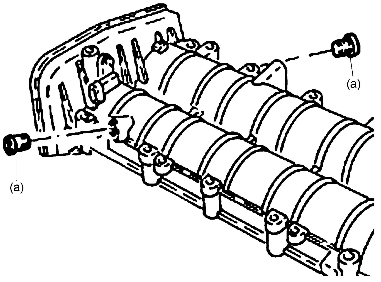
Tighten camshaft housing plugs to specified torque.
14)Tighten new oil pump bolt to specified torque.
15)Install EGR-2 valve bracket.
16)Install engine right mounting bracket (1), and tighten engine right mounting bracket bolts to specified torque.
Engine right mounting bracket bolt (M8) (b): 26 N·m (2.7 kgf-m, 19.5 lbf-ft)
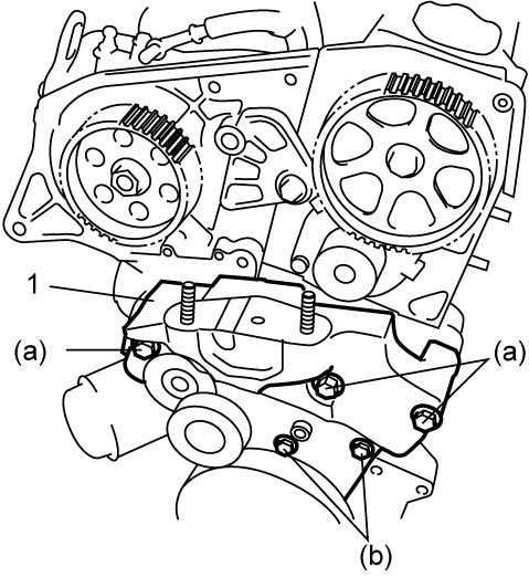
Tightening torque
Engine right mounting bracket bolt (M10) (a): 50 N·m (5.1 kgf-m, 37.0 lbf-ft)Engine right mounting bracket bolt (M8) (b): 26 N·m (2.7 kgf-m, 19.5 lbf-ft)
17)Install timing belt cover.
19)Install crankshaft pulley (1) and tighten bolts to specified torque.
21)Install engine assembly.