Engine Assembly Removal and Installation
Precautions: General safety (00)
Removal
1)Remove battery and battery tray from vehicle. 
2)Remove engine cover.
3)Relieve fuel pressure.
4)Remove air cleaner assembly and MAF sensor with IAT sensor-1.
5)For M/T model, disconnect gear shift and gear select control cables from transaxle.
6)For twin clutch system model, disconnect parking cable from transaxle.
7)For M/T model, disconnect clutch fluid pipe.
8)Hoist vehicle and remove engine undercover.
9)Remove front bumper.
10)Drain coolant.
11)Drain engine oil.
12)Drain transaxle oil.
•M/T model:
•Twin clutch system model:
•Twin clutch system model:
13)For 4WD model, drain transfer oil.
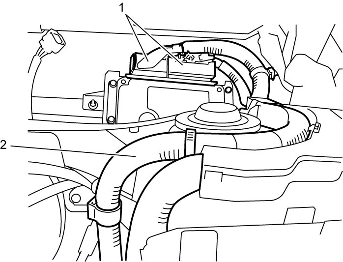
14)Disconnect ECM connectors (1) and remove engine harness (2) from harness clamp.

15)Remove generator drive belt.
16)With A/C hose connected, detach A/C compressor from its bracket and using a rope, hold A/C compressor in a place where no damage will be caused.
•Manual A/C model:
•Auto A/C model:
•Auto A/C model:
17)Remove air cleaner bracket (1).
18)Disconnect the following electric wires:
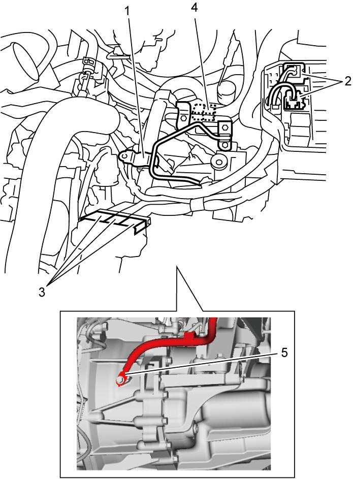
•Relay box (2)
•Main fuse box (3)
•Injector harness (4)
•Ground wire (M/T model) (5)
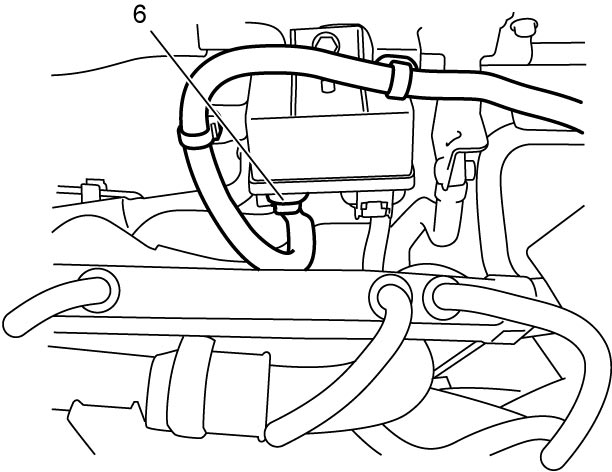
•Glow plug control module (6)
•Compressor ON/OFF valve connector
•Each wire harness
•Twin clutch system connectors (twin clutch system model)
•Electric motor connector (twin clutch system model)
•Main fuse box (3)
•Injector harness (4)
•Ground wire (M/T model) (5)
•Glow plug control module (6)
•Compressor ON/OFF valve connector
•Each wire harness
•Twin clutch system connectors (twin clutch system model)
•Electric motor connector (twin clutch system model)
19)Disconnect the following pipes and hoses:
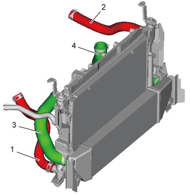
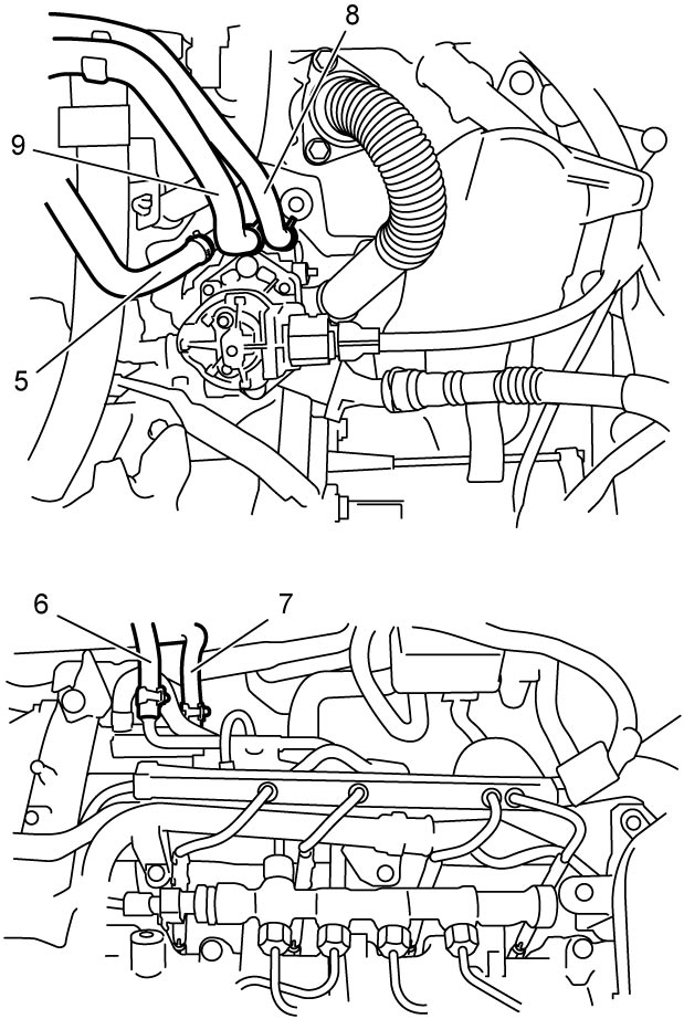
•Radiator inlet hose (2) and outlet hose (1)
•Degassing tank inlet hose
•Intercooler inlet hose (3) and outlet hose (4)
•Heater inlet hose (5) and outlet hose
•Fuel return hose (6)
•Fuel feed hose (7)
•Air cleaner outlet No.1 hose
•Brake booster vacuum hose
•Differential pressure sensor hose No.1 (8) and No.2 (9)
•Degassing tank inlet hose
•Intercooler inlet hose (3) and outlet hose (4)
•Heater inlet hose (5) and outlet hose
•Fuel return hose (6)
•Fuel feed hose (7)
•Air cleaner outlet No.1 hose
•Brake booster vacuum hose
•Differential pressure sensor hose No.1 (8) and No.2 (9)
20)Remove exhaust No.1 pipe.
21)For 4WD model, remove propeller shaft.
22)Disconnect right and left drive shaft joints from steering knuckle.
23)Disconnect steering lower shaft from pinion shaft.
24)Remove suspension frame.
25)Support engine and transaxle using jack.
26)Remove engine right mounting bracket bolt (1), nuts (2) and left mounting bracket bolt (3) and nuts (4).
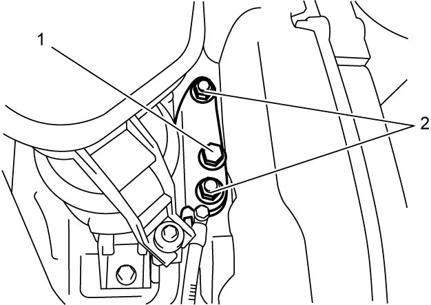
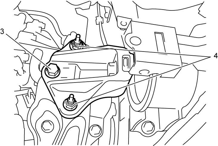
27)Before lowering engine, check that all hoses, electric wires and cables are disconnected from engine.
28)Lower engine assembly, transaxle, drive shafts and transfer (4WD model) together.
NOTICE:
The A/C compressor may be damaged if it hits against or interferes with other parts.
Suspend the removed A/C compressor in a place where no damage will be caused during removal of the engine assembly.
29)Remove injection harness from engine assembly, if necessary.
30)Remove right and left drive shafts, if necessary.
31)For 4WD model, remove transfer, if necessary.
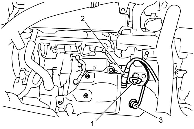
NOTICE:
When lifting engine assembly using chain hoist or the like with engine hook (1), chain or hook may interfere with A/F sensor-1 (2) and EGT sensor-1 (3) including their harnesses and damage them.
Before lifting engine assembly using chain hoist, remove A/F sensor-1 and EGT sensor-1.
32)Remove transaxle, if necessary.
•M/T model:
•Twin clutch system model:
•Twin clutch system model:
33)For M/T model, remove clutch cover and clutch disc, if necessary.
Installation
1)For M/T model, install clutch cover and clutch disc, if removed.
2)For twin clutch system model, adjust flywheel preload.
3)Install transaxle, if removed.
•M/T model:
•Twin clutch system model:
•Twin clutch system model:
4)For 4WD model, install transfer, if removed.
5)Connect right and left drive shafts, if removed.
6)Install injection harness from engine assembly and tighten the following nuts to specified torque, if removed.
•“B” terminal nut:
•Magnetic switch lead wire nut and battery cable nut:
•Magnetic switch lead wire nut and battery cable nut:
7)Lift engine assembly with transaxle, drive shafts and transfer (4WD model).
NOTICE:
The A/C compressor may be damaged if it hits against or interferes with other parts.
Suspend the removed A/C compressor in a place where no damage will be caused during installation of the engine assembly.
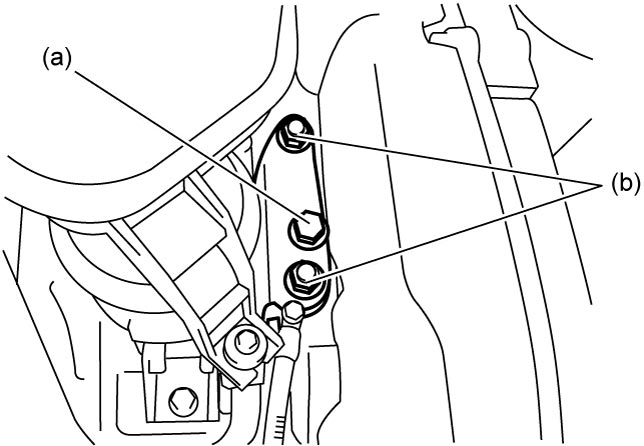
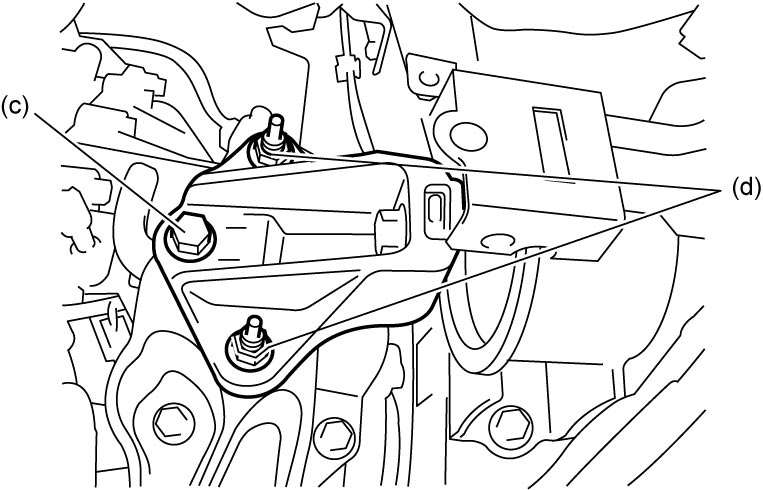
8)Install the following bolts and nuts, and tighten them to specified torque.
Engine right mounting nut (b): 93 N·m (9.5 kgf-m, 68.5 lbf-ft)
Engine left mounting bracket bolt (M/T model) (c): 55 N·m (5.6 kgf-m, 40.5 lbf-ft)
Engine left mounting bracket bolt (Twin clutch system model) (c): 93 N·m (9.5 kgf-m, 68.5 lbf-ft)
Engine left mounting bracket nut (d): 55 N·m (5.6 kgf-m, 40.5 lbf-ft)
Tightening torque
Engine right mounting bolt (a): 93 N·m (9.5 kgf-m, 68.5 lbf-ft)Engine right mounting nut (b): 93 N·m (9.5 kgf-m, 68.5 lbf-ft)
Engine left mounting bracket bolt (M/T model) (c): 55 N·m (5.6 kgf-m, 40.5 lbf-ft)
Engine left mounting bracket bolt (Twin clutch system model) (c): 93 N·m (9.5 kgf-m, 68.5 lbf-ft)
Engine left mounting bracket nut (d): 55 N·m (5.6 kgf-m, 40.5 lbf-ft)
9)Remove jack.
10)Install suspension frame.
11)Connect right and left drive shaft joints to steering knuckle.
12)Connect steering lower shaft to pinion shaft.
13)For 4WD model, install propeller shaft.
14)Install exhaust No.1 pipe.
15)Install A/C compressor to its bracket.
•Manual A/C model:
•Auto A/C model:
•Auto A/C model:
16)Install generator drive belt.
17)Reinstall disconnected hoses, pipes, cables and electric wires.
18)Install air cleaner bracket.
19)Install engine harness to harness clamp and connect it to ECM.
20)For 4WD model, refill transfer with oil.
21)Refill transaxle with oil.
•M/T model:
•Twin clutch system model:
•Twin clutch system model:
22)Refill engine with engine oil.
23)Refill cooling system with coolant.
24)For M/T model, connect clutch fluid pipe.
25)For twin clutch system model, connect parking cable to transaxle.
26)For M/T model, connect gear shift and gear select control cables to transaxle.
27)Install air cleaner assembly and MAF sensor with IAT sensor-1.
28)Install battery and battery tray to vehicle.
29)Check that all removed parts are installed at original positions.
30)Check any leakage of coolant, oil, fuel and exhaust gases.
•For fuel leakage:
•For coolant leakage:
•For coolant leakage:
31)Install front bumper.
32)Install engine undercover.
33)Install engine cover.