Radiator Cooling Fan System Check
Precautions: Precautions for Cooling System · General safety (00)
Circuit Diagram
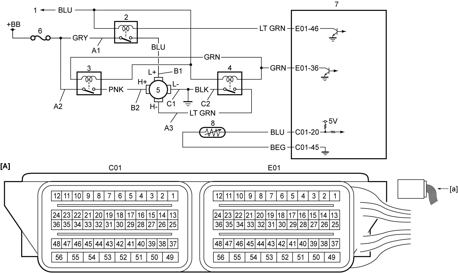
| [A]: | ECM connector (View: [a]) | C1: | Radiator cooling fan motor ground circuit | 5. | Radiator cooling fan motor |
| A1: | Radiator cooling fan relay No.1 power supply circuit (switch side) | C2: | Radiator cooling fan relay No.3 ground circuit | 6. | “RDTR” fuse |
| A2: | Radiator cooling fan relay No.2 power supply circuit (switch side) | 1. | To main relay | 7. | ECM |
| A3: | Radiator cooling fan relay No.3 power supply circuit (switch side) | 2. | Radiator cooling fan relay No.1 | 8. | ECT sensor |
| B1: | Radiator cooling fan motor drive circuit (low speed) | 3. | Radiator cooling fan relay No.2 | ||
| B2: | Radiator cooling fan motor drive circuit (high speed) | 4. | Radiator cooling fan relay No.3 |
Troubleshooting
NOTE:
•For details of engine cooling fan operation, refer to Cooling Fan Operation Description:M16A.
•Before beginning troubleshooting, read Precautions for Engine (M16A).
•When measuring circuit voltage, resistance and/or pulse signal of ECM, refer to Inspection of ECM and Its Circuits:M16A.
•Before beginning troubleshooting, read Precautions for Engine (M16A).
•When measuring circuit voltage, resistance and/or pulse signal of ECM, refer to Inspection of ECM and Its Circuits:M16A.
| Step | Action | Yes | No |
|---|---|---|---|
| 1 |
DTC check
1)Set ignition “OFF” and connect SUZUKI scan tool to DLC.
2)Set ignition “ON” and check DTC.
Is there DTC(s)?
|
Go to applicable DTC troubleshooting and recheck DTC.
|
Go to Step 2.
|
| 2 |
Radiator cooling fan low-speed operation control check
1)Check radiator cooling fan control for low-speed operation.

Is check result OK?
|
Go to Step 3.
|
Go to Step 4.
|
| 3 |
Radiator cooling fan high-speed operation control check
1)Check radiator cooling fan control for high-speed operation.
Is check result OK?
|
Radiator cooling fan control system is in good condition.
|
Go to Step 8.
|
| 4 |
Radiator cooling fan relay No.1 power supply circuit (switch side) check
1)Set ignition “OFF” and remove radiator cooling fan relay No.1 from individual circuit fuse box No.1.
2)Check for proper connection to radiator cooling fan relay No.1 at each terminal.
3)If OK, measure voltage between “A1” circuit and ground.
Is it 10 – 14 V?
|
Go to Step 5.
|
Repair “A1” circuit.
|
| 5 |
Radiator cooling fan relay No.1 check
1) Check radiator cooling fan relay No.1.
Is check result OK?
|
Go to Step 6.
|
Replace radiator cooling fan relay No.1.
|
| 6 |
Radiator cooling fan motor drive circuit (low speed) check
1)Set ignition “OFF” and disconnect radiator cooling fan motor connector.
2)Check for proper connection to radiator cooling fan motor at each terminal.
3)If OK, check the following points.
•Resistance of “B1” circuit: 1 Ω or less
•Resistance between “B1” circuit and ground: infinity •Voltage of “B1” circuit: approx. 0 V (With ignition is “ON”) Is check result OK?
|
Go to Step 7.
|
Repair “B1” circuit.
|
| 7 |
Radiator cooling fan motor ground circuit check
1)Measure resistance between “C1” circuit and ground.
Is resistance 1 Ω or less?
|
Go to Step 14.
|
Repair “C1” circuit.
|
| 8 |
Radiator cooling fan relay No.2 power supply circuit (switch side) check
1)Set ignition “OFF” and remove radiator cooling fan relay No.2 from individual circuit fuse box No.1.
2)Check for proper connection to radiator cooling fan relay No.2 at each terminal.
3)If OK, measure voltage between “A2” circuit and ground.
Is it 10 – 14 V?
|
Go to Step 9.
|
Repair “A2” circuit.
|
| 9 |
Radiator cooling fan relay No.2 check
1)Check radiator cooling fan relay No.2.
Is check result OK?
|
Go to Step 10.
|
Replace radiator cooling fan relay No.2.
|
| 10 |
Radiator cooling fan motor drive circuit (high speed) check
1)Set ignition “OFF” and disconnect radiator cooling fan motor connector.
2)Check for proper connection to radiator cooling motor at each terminal.
3)If OK, check the following points.
•Resistance of “B2” circuit: 1 Ω or less
•Resistance between “B2” circuit and ground: infinity •Voltage of “B2” circuit: approx. 0 V (When ignition is “ON”) Is check result OK?
|
Go to Step 11.
|
Repair “B2” circuit.
|
| 11 |
Radiator cooling fan relay No.3 power supply circuit (switch side) check
1)Set ignition “OFF” and remove radiator cooling fan relay No.3 from individual circuit fuse box No.1.
2)Check for proper connection to radiator cooling fan relay No.3 at each terminal.
3)If OK, check the following points.
•Resistance of “A3” circuit: 1 Ω or less
•Resistance between “A3” circuit and ground: infinity •Voltage of “A3” circuit: approx. 0 V (When ignition is “ON”) Is check result OK?
|
Go to Step 12.
|
Repair “A3” circuit.
|
| 12 |
Radiator cooling fan relay No.3 check
1)Check radiator cooling fan relay No.3.
Is check result OK?
|
Go to Step 13.
|
Replace radiator cooling fan relay No.3.
|
| 13 |
Radiator cooling fan relay No.3 ground circuit check
1)Measure resistance between “C2” circuit and ground.
Is resistance 1 Ω or less?
|
Go to Step 14.
|
Repair “C2” circuit.
|
| 14 |
Radiator cooling fan motor check
1)Check radiator cooling fan motor.
Is check result OK?
|
Replace ECM and recheck radiator cooling fan system.
|
Replace radiator cooling fan motor.
|