Fuel Injector Circuit Check
Precautions: Precautions for Fuel System Service · General safety (00)
Circuit Diagram
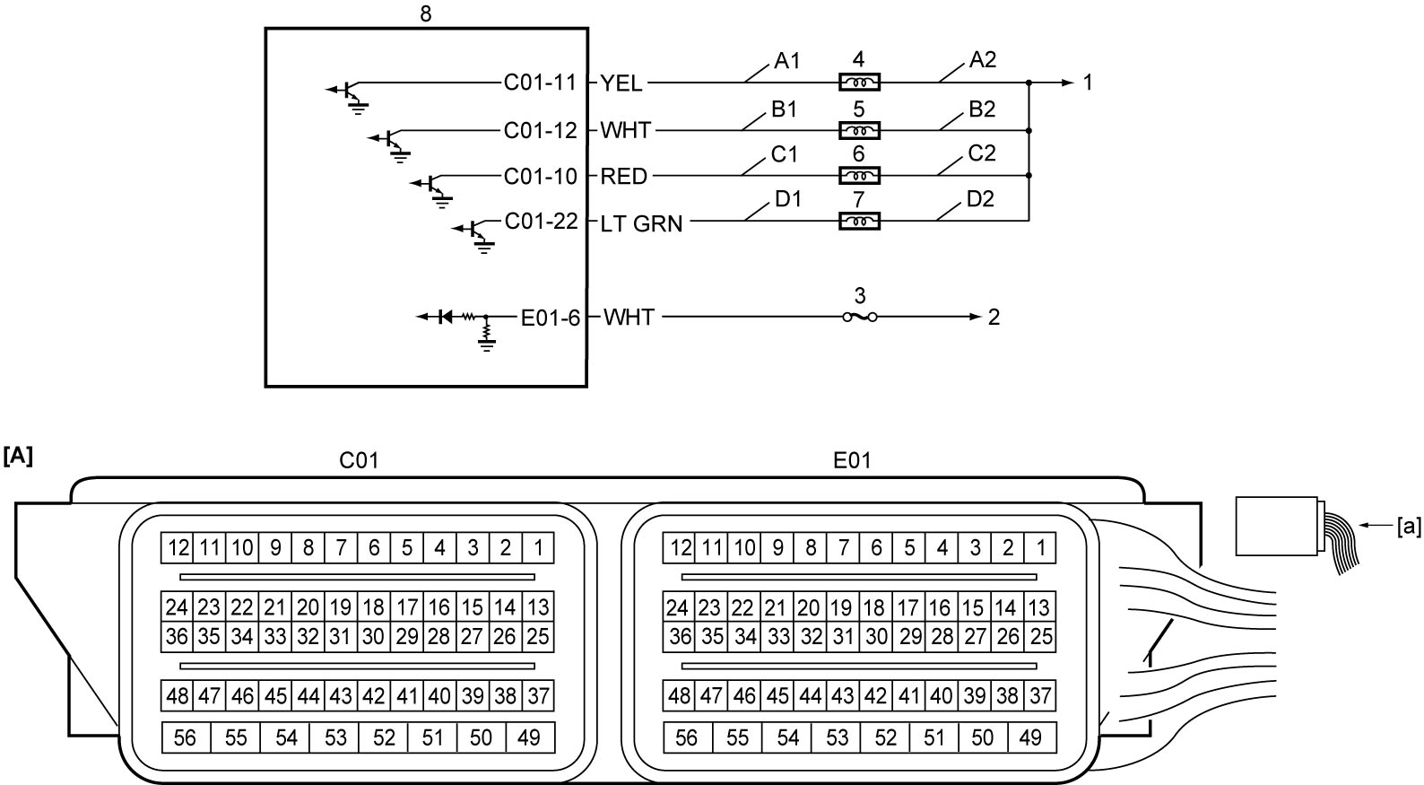
| [A]: | ECM connector (View: [a]) | C2: | Fuel injector No.3 power supply circuit | 4. | Fuel injector No.1 |
| A1: | Fuel injector No.1 drive circuit | D1: | Fuel injector No.4 drive circuit | 5. | Fuel injector No.2 |
| A2: | Fuel injector No.1 power supply circuit | D2: | Fuel injector No.4 power supply circuit | 6. | Fuel injector No.3 |
| B1: | Fuel injector No.2 drive circuit | 1. | To main relay | 7. | Fuel injector No.4 |
| B2: | Fuel injector No.2 power supply circuit | 2. | To ignition switch (ignition switch model) or IG1 relay (keyless push start model) | 8. | ECM |
| C1: | Fuel injector No.3 drive circuit | 3. | “IG COIL” fuse |
Troubleshooting
| Step | Action | Yes | No |
|---|---|---|---|
| 1 |
Fuel injector check for operating sound
1)Remove air cleaner assembly.

2)Using sound scope, check each fuel injector for operating sound at engine cranking.
Do all fuel injectors make operating sound?
|
Fuel injectors circuit is in good condition.
|
Go to Step 2.
|
| 2 |
Fuel injector resistance check
1)When ignition is “OFF”, disconnect connectors from fuel injectors.
2)Check for proper terminal connection to fuel injector connectors.
3)If OK, check all fuel injectors for resistance.
Is check result OK?
|
Go to Step 3.
|
Replace fuel injector.
|
| 3 |
Fuel injector insulation resistance check
1)Check that resistance between each fuel injector terminal and ground is infinity.
Is check result OK?
|
Go to Step 4.
|
Replace fuel injector.
|
| 4 |
Fuel injector power supply circuit check
1)Set ignition “ON”.
2)Check that voltage between each of “A2”, “B2”, “C2” and “D2” and ground is battery voltage.
Is check result OK?
|
Go to Step 5.
|
Repair fuel injector power supply circuit.
If it is in good condition, go to ECM Power Supply and Ground Circuit Check:M16A.
|
| 5 |
Fuel injector drive circuit check
1)When ignition is “OFF”, disconnect “C01” and “E01” connectors from ECM.
2)If connections are OK, check the following points.
•Resistance of “A1”, “B1”, “C1” and “D1”: less than 1 Ω
•Resistance between each of “A1”, “B1”, “C1” and “D1” circuits and ground: infinity •Resistance between each of “A1” circuit terminal and other terminal at fuel injector connector: infinity •Resistance between each of “B1” circuit terminal and other terminal at fuel injector connector: infinity •Resistance between each of “C1” circuit terminal and other terminal at fuel injector connector: infinity •Resistance between each of “D1” circuit terminal and other terminal at fuel injector connector: infinity •Voltage of “A1” – “D1” circuits: approx. 0 V (When ignition is “ON”) Is check result OK?
|
Go to Step 6.
|
Repair fuel injector drive circuit.
|
| 6 |
Fuel injector check
1)Check fuel injector.
Is check result OK?
|
Replace ECM and recheck DTC.
|
Replace fuel injector.
|