ECM Power Supply and Ground Circuit Check
Precautions: General safety (00)
Circuit Diagram
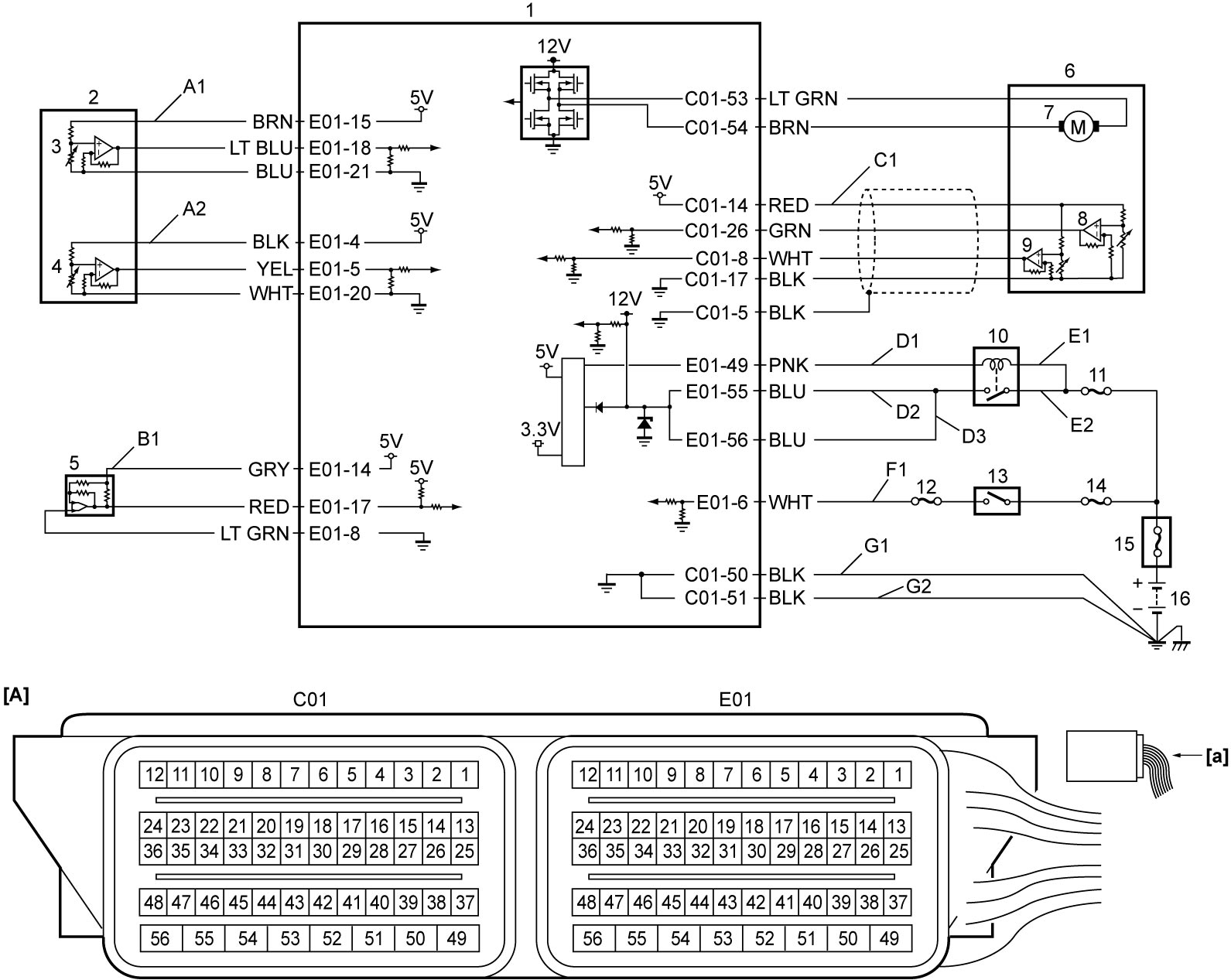
| [A]: | ECM connector (View: [a]) | F1: | Ignition ON signal circuit | 8. | TP sensor (main) |
| A1: | APP sensor (main) power supply circuit | G1: | ECM ground circuit 1 | 9. | TP sensor (sub) |
| A2: | APP sensor (sub) power supply circuit | G2: | ECM ground circuit 2 | 10. | Main relay |
| B1: | A/C refrigerant pressure sensor power supply circuit | 1. | ECM | 11. | “FI” fuse |
| C1: | TP sensor power supply circuit | 2. | APP sensor | 12. | “IG COIL” fuse |
| D1: | Main relay drive circuit | 3. | APP sensor (main) | 13. | Ignition switch (ignition switch model) or IG1 relay (keyless push start model) |
| D2: | Main power supply circuit 2 | 4. | APP sensor (sub) | 14. | “IGN” fuse |
| D3: | Main power supply circuit 1 | 5. | A/C refrigerant pressure sensor (A/C model) | 15. | Main fuse box |
| E1: | Main relay power supply circuit (coil side) | 6. | Electric throttle body assembly | 16. | Battery |
| E2: | Main relay power supply circuit (switch side) | 7. | Throttle actuator |
Circuit Description
When ignition is set to “ON”, the main relay turns on (contacts close) and the main power is supplied to ECM. ECM then supplies 5 V power to the following sensors: A/C refrigerant pressure sensor (A/C model), APP sensor and TP sensor.
Troubleshooting
NOTE:
•Before troubleshooting, read “Precautions for ECM Circuit Inspection” under Precautions for Engine (M16A).
•Before performing, check that related fuses of ECM power circuit have not blown out.
If any fuse has blown out, replace the fuse and check circuits connected to the blown fuse for short circuit to ground.
•Before performing, check that related fuses of ECM power circuit have not blown out.
If any fuse has blown out, replace the fuse and check circuits connected to the blown fuse for short circuit to ground.
| Step | Action | Yes | No |
|---|---|---|---|
| 1 |
Battery check
1)Check that battery voltage is 12 V or more.
Is check result OK?
|
Go to Step 2.
|
Check battery and generator referring to Battery Inspection:M16A and Generator Test:M16A.
|
| 2 |
Main relay power supply check
1)With ignition “OFF”, remove main relay (1) from individual circuit fuse box No.1.
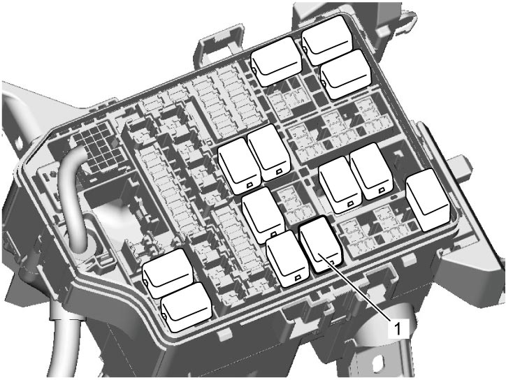
2)Check for proper terminal connection to main relay connector.
3)If connection is OK, set ignition “ON”.
4)Check that voltage between each of “E1” and “E2” circuit and ground is battery voltage.
Is check result OK?
|
Go to Step 3.
|
Check that “FI” fuse has not blown. If check result is OK, repair or replace defective wire harness.
|
| 3 |
Main relay check
1)Check main relay.

Is check result OK?
|
Go to Step 4.
|
Replace main relay.
|
| 4 |
Ignition mode circuit check
1)With ignition “OFF”, install main relay to individual circuit fuse box No.1.
2)Disconnect “C01” and “E01” connectors from ECM.
3)Check for proper terminal connection to “C01” and “E01” connectors.
4)If connections are OK, set ignition “ON”.
5)Check that voltage between “F1” and ground is battery voltage.
Is check result OK?
|
Go to Step 5.
|
Check that “IG COIL” fuse or “IGN” fuse has not blown. If check result is OK, repair or replace defective wire harness.
|
| 5 |
Main relay drive circuit check
1)Set ignition “OFF”.
2)Check that voltage between “D1” and ground is battery voltage.
Is check result OK?
|
Go to Step 6.
|
Repair or replace defective wire harness.
|
| 6 |
Main power supply circuit check
1)Using service wire, ground “D1”.
2)Set ignition “ON”.
3)Check that voltage between each of “D2” and “D3” circuit and ground is battery voltage.
Is check result OK?
|
Go to Step 7.
|
Repair or replace defective wire harness.
|
| 7 |
ECM ground circuit check
1)Set ignition “OFF”.
2)Check that resistance between each of “G1” and “G2” circuit and ground is less than 1 Ω.
Is check result OK?
|
Go to Step 8.
|
Repair or replace defective wire harness.
|
| 8 |
Sensor power supply circuit check
1)With ignition “OFF”, connect “C01” and “E01” connectors to ECM.
2)Disconnect connectors from APP sensor, electric throttle body assembly and A/C refrigerant pressure sensor (A/C model).
3)Check for proper terminal connection to each sensor connector.
4)If connections are OK, set ignition “ON”.
5)Check that voltage between each of the following circuits and ground is approx. 5 V.
•A1
•A2 •B1 •C1 Is check result OK?
|
ECM power supply and ground circuits are in good condition.
|
Check wiring harness for open, short circuit to battery and short circuit to ground. If wiring harness is in good condition, replace ECM and recheck ECM power supply and ground circuits.
|