Ignition System Check
Precautions: General safety (00)
Circuit Diagram
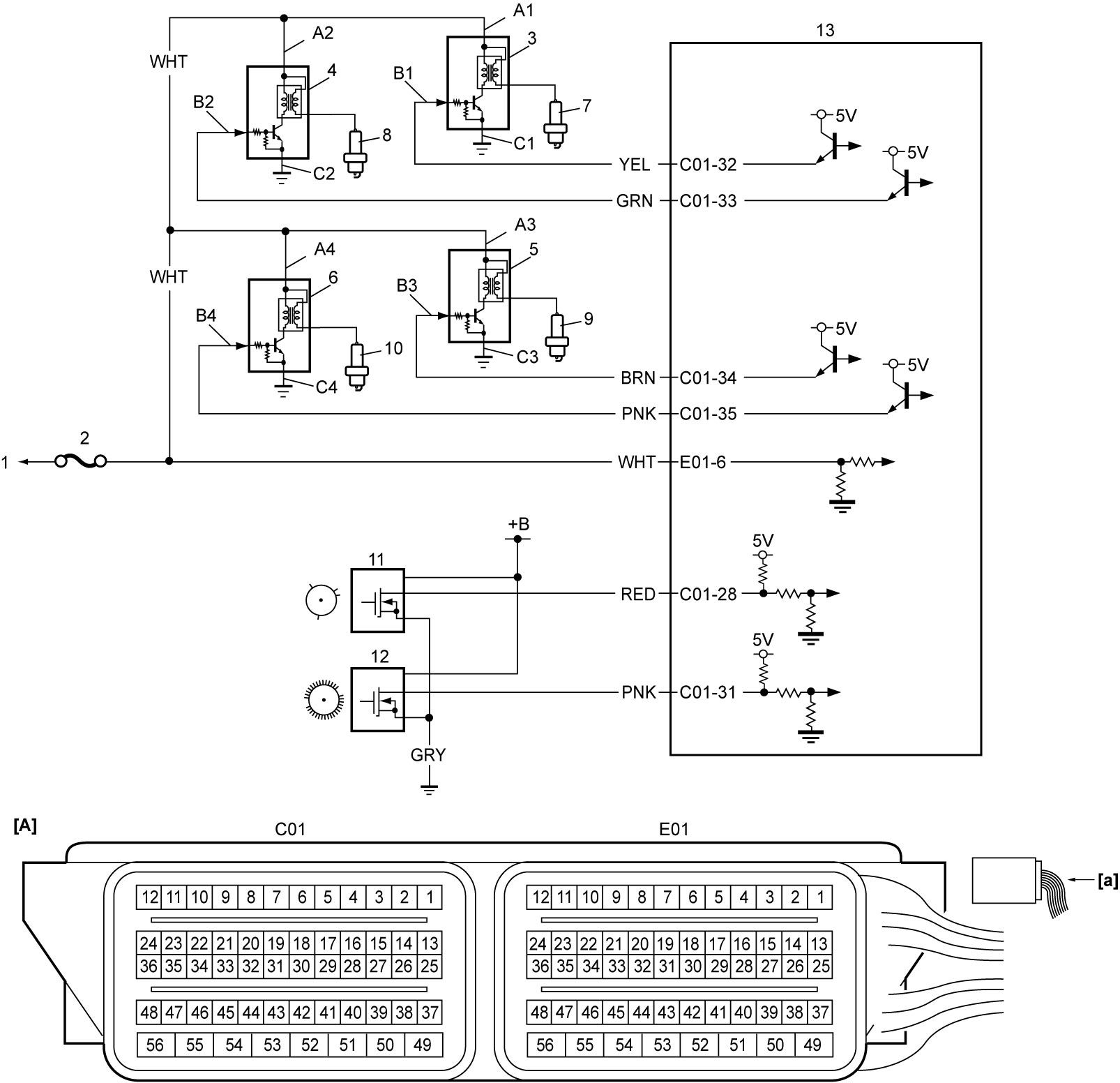
| [A]: | ECM connector (View: [a]) | 3. | Ignition coil assembly No.1 | 9. | Spark plug No.3 |
| A1 – A4: | Ignition coil assembly power supply circuits | 4. | Ignition coil assembly No.2 | 10. | Spark plug No.4 |
| B1 – B4: | Ignition coil assembly drive circuits | 5. | Ignition coil assembly No.3 | 11. | CMP sensor |
| C1 – C4: | Ignition coil assembly ground circuits | 6. | Ignition coil assembly No.4 | 12. | CKP sensor |
| 1. | To ignition switch (ignition switch model) or IG1 relay (keyless push start model) | 7. | Spark plug No.1 | 13. | ECM |
| 2. | “IG COIL” fuse | 8. | Spark plug No.2 |
Troubleshooting
| Step | Action | Yes | No |
|---|---|---|---|
| 1 |
Was “Engine and Emission Control System Check” performed?
|
Go to Step 2.
|
|
| 2 |
Ignition spark test 1
1)Perform ignition spark test.

Is test result OK?
|
Go to Step 3.
|
Go to Step 4.
|
| 3 |
Ignition timing check
1)Check ignition timing.
Is check result OK?
|
Ignition system is in good condition.
|
Repair or replace defective part.
|
| 4 |
Confirmation of malfunctioning cylinder
1)Check cylinder(s) that failed in ignition spark test.
Did all cylinders fail in ignition spark test?
|
Go to Step 7.
|
Go to Step 5.
|
| 5 |
Ignition spark test 2
1)Replace spark plug of each malfunctioning cylinder with normal cylinder’s one.
2)Perform ignition spark test.
Is test result OK?
|
Replace spark plug.
|
Go to Step 6.
|
| 6 |
Ignition spark test 3
1)Replace ignition coil of each malfunctioning cylinder with normal cylinder’s one.
2)Perform ignition spark test.
Is test result OK?
|
Replace ignition coil.
|
Go to Step 7.
|
| 7 |
Ignition coil assembly power supply and ground circuit check
1)Check power supply (“A1”, “A2”, “A3” and “A4”) and ground (“C1”, “C2”, “C3” and “C4”) circuits of each ignition coil assembly for open, short and poor connection.
Is check result OK?
|
Go to Step 8.
|
Repair or replace defective wiring harness.
|
| 8 |
Ignition coil assembly drive circuit check
1)When ignition is “OFF”, check the following points.
•Resistance of “B1”, “B2”, “B3” and “B4” circuits: less than 1 Ω
•Resistance between each of “B1”, “B2”, “B3” and “B4” circuits and ground: infinity •Resistance between “B1” circuit terminal and other terminal at ignition coil connector: infinity •Resistance between “B2” circuit terminal and other terminal at ignition coil connector: infinity •Resistance between “B3” circuit terminal and other terminal at ignition coil connector: infinity •Resistance between “B4” circuit terminal and other terminal at ignition coil connector: infinity •Voltage of “B1”, “B2”, “B3” and “B4” circuits: 0 to 1 V (When ignition is “ON”) Is check result OK?
|
Go to Step 9.
|
Repair or replace defective wiring harness.
|
| 9 |
CKP sensor and CMP sensor check
1)Check CKP sensor and CMP sensor.
•CKP sensor:
•CMP sensor: Is check result OK?
|
Replace ECM and recheck ignition spark.
|
Replace CKP sensor or CMP sensor.
|