ESP® Circuit Diagram
Precautions: Precautions for ESP® · Precautions for Diagnosing Trouble · Test with Speedometer Tester or Other Equipment · Precautions for Brakes · General safety (00)
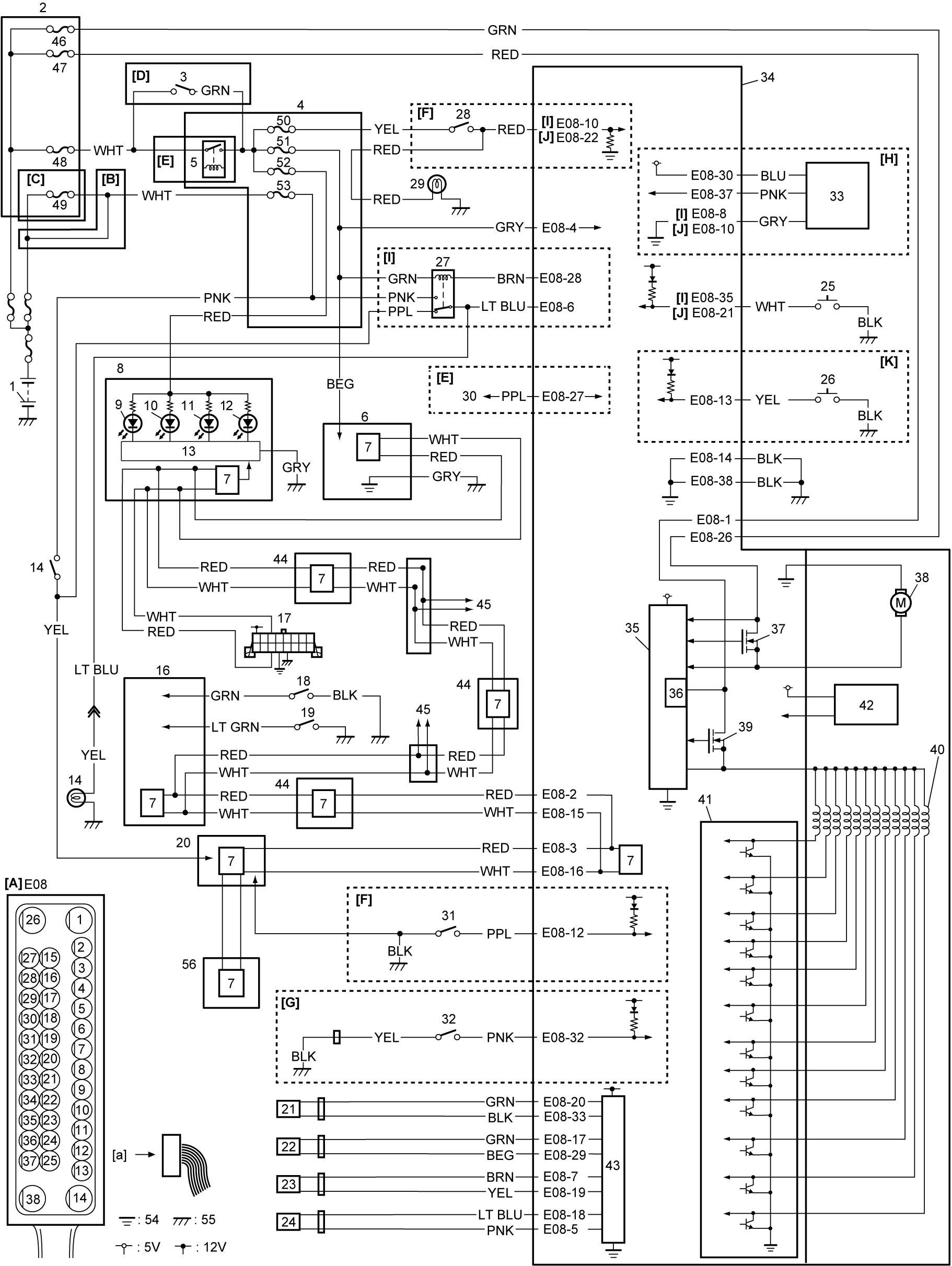
| [A]: | ESP® hydraulic unit / control module assembly connector (View: [a]) | 13. | CPU (combination meter) | 36. | Internal memory |
| [B]: | Petrol engine model | 14. | Brake light switch | 37. | Pump motor relay |
| [C]: | Diesel engine model | 15. | Brake light | 38. | Pump motor |
| [D]: | Ignition switch model | 16. | BCM | 39. | Solenoid valve power supply relay |
| [E]: | Keyless push start model | 17. | DLC | 40. | Solenoid valve |
| [F]: | With hill hold control or hill descent control (M/T model) | 18. | Brake fluid level switch | 41. | Solenoid valve relay |
| [G]: | With hill hold control or hill descent control without ENG A-STOP (M/T model) | 19. | Parking brake switch | 42. | Yaw rate / G sensor |
| [H]: | ENG A-STOP model | 20. | ECM | 43. | Wheel speed sensor driver |
| [I]: | RBS model | 21. | Left-front wheel speed sensor | 44. | Other control modules (if equipped) |
| [J]: | Non-RBS model | 22. | Right-front wheel speed sensor | 45. | To other control modules by CAN |
| [K]: | 4WD model | 23. | Left-rear wheel speed sensor | 46. | “ABS” fuse (25A) |
| 1. | Battery | 24. | Right-rear wheel speed sensor | 47. | “ABS SOL” fuse |
| 2. | Relay box | 25. | ESP® OFF switch | 48. | “IGN” fuse |
| 3. | Ignition switch | 26. | Hill descent control switch (if equipped) | 49. | “BTRY” fuse |
| 4. | J/B | 27. | Brake light relay (if equipped) | 50. | “BACK” fuse |
| 5. | IG1 relay | 28. | Back up light switch | 51. | “ABS” fuse (10A) |
| 6. | Steering angle sensor | 29. | Back up light | 52. | “MTR” fuse |
| 7. | CAN driver | 30. | To keyless start control module | 53. | “STOP” fuse |
| 8. | Combination meter | 31. | CPP No.2 switch | 54. | Engine ground |
| 9. | ESP® OFF light | 32. | Neutral position switch | 55. | Ground |
| 10. | ESP® warning light | 33. | Brake booster pressure sensor | 56. | TCM (A/T model) |
| 11. | ABS warning light | 34. | ESP® hydraulic unit / control module assembly | ||
| 12. | EBD warning light (brake warning light) | 35. | CPU |
| Terminal | Wire color | Circuit |
|---|---|---|
| 1 | RED | Solenoid valve power supply circuit |
| 2 | RED | CAN communication line (high) for BCM |
| 3 | RED | CAN communication line (high) for ECM |
| 4 | GRY | Ignition power supply circuit |
| 5 | PNK | Right-rear wheel speed sensor signal circuit |
| 6 | LT BLU | Brake light relay signal circuit |
| 7 | BRN | Left-rear wheel speed sensor power supply circuit |
| 8 | GRY | Brake booster pressure sensor ground circuit (RBS model) |
| 10 | GRY | Brake booster pressure sensor ground circuit (Non-RBS model) / Back up light switch signal circuit (RBS model) |
| 12 | PPL | CPP No.2 switch signal circuit |
| 13 | YEL | Hill descent control switch signal circuit (if equipped) |
| 14 | BLK | ESP® control module ground circuit 1 |
| 15 | WHT | CAN communication line (low) for BCM |
| 16 | WHT | CAN communication line (low) for ECM |
| 17 | GRN | Right-front wheel speed sensor power supply circuit |
| 18 | LT BLU | Right-rear wheel speed sensor power supply circuit |
| 19 | YEL | Left-rear wheel speed sensor signal circuit |
| 20 | GRN | Left-front wheel speed sensor power supply circuit |
| 21 | WHT | ESP® OFF switch signal circuit (Non-RBS model) |
| 22 | RED | Back up light switch signal circuit (Non-RBS model) |
| 26 | GRN | Pump motor power supply circuit |
| 27 | PPL | Vehicle speed output circuit |
| 28 | BRN | Brake light relay drive circuit |
| 29 | BEG | Right-front wheel speed sensor signal circuit |
| 30 | BLU | Brake booster pressure sensor power supply circuit |
| 32 | PNK | Neutral position switch signal circuit |
| 33 | BLK | Left-front wheel speed sensor signal circuit |
| 35 | WHT | ESP® OFF switch signal circuit (RBS model) |
| 37 | PNK | Brake booster pressure sensor signal circuit |
| 38 | BLK | ESP® control module ground circuit 2 |