DTC C1061
Precautions: Precautions for ESP® · Precautions for Diagnosing Trouble · Test with Speedometer Tester or Other Equipment · Precautions for Brakes · General safety (00)
DTC Detecting Condition and Trouble Area
| DTC detecting condition | Trouble area |
|---|---|
|
C1061: Pump Motor Circuit Performance
•Pump motor power supply voltage is out of specified range.
•When pump motor is activated, a malfunction in pump motor is detected. •Power supply from CPU to pump motor and pump motor relay monitor data disagree. |
•ESP® control module (pump motor) power supply circuit
•ESP® control module ground circuit •ESP® control module |
Circuit Diagram
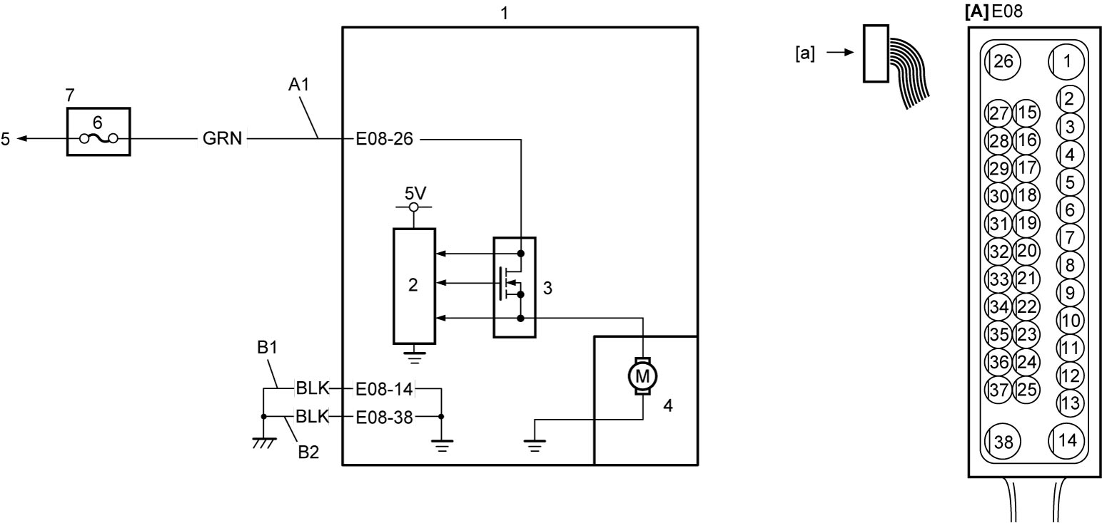
| [A]: | ESP® control module connector (View: [a]) | 1. | ESP® control module | 5. | Lead to battery |
| A1: | Pump motor power supply circuit | 2. | CPU | 6. | “ABS” fuse (25A) |
| B1: | ESP® control module ground circuit 1 | 3. | Pump motor relay | 7. | Relay box |
| B2: | ESP® control module ground circuit 2 | 4. | Pump motor |
DTC Troubleshooting
| Step | Action | Yes | No |
|---|---|---|---|
| 1 |
Was “ESP® System Check” performed?
|
Go to Step 2.
|
Go to ESP® System Check.
|
| 2 |
ESP® control module power supply circuit check
1)Check that ignition is “OFF”.
2)Disconnect “E08” connector.
3)Check for proper connection to “E08” connector.
4)If connection is OK, measure voltage between “E08-26” terminal and ground.
Is it 10 – 14 V?
|
Go to Step 3.
|
Repair or replace “A1” circuit.
|
| 3 |
ESP® control module ground circuit check
1)Measure resistance between each of “E08-14” and “E08-38” terminals and ground.
Is resistance less than 1 Ω?
|
Replace ESP® hydraulic unit / control module assembly and recheck DTC.

|
Repair or replace “B1” circuit and/or “B2” circuit.
|