ESP® Hydraulic Unit / Control Module Assembly Removal and Installation
Precautions: Precautions for ESP® · Precautions for Diagnosing Trouble · Test with Speedometer Tester or Other Equipment · Precautions for Brakes · General safety (00)
NOTICE:
•Performing the following prohibited operations will affect the original performance of ESP® hydraulic unit / control module assembly.
•The bracket of the ESP® hydraulic unit / control module assembly may have some burrs at the edge and may damage or deformation the bushing, resulting in abnormal operation of the ESP® system.
Be careful not to scratch bushings with the burr of the bracket when removing / installing the ESP® hydraulic unit / control module assembly from / to the bracket.
—Do not disassemble the ESP® hydraulic unit / control module assembly.
—Do not loosen the blind plug.
—Do not remove the motor.
—Regarding ESP® hydraulic unit / control module assembly removal and installation, check specified torque and do not use impact tool.
—Use care not to allow dust to enter ESP® hydraulic unit / control module.
—Do not place ESP® hydraulic unit / control module on its side or upside down.
—Do not give an impact to hydraulic unit.
•Brake fluid is extremely damaging to painted surfaces. If brake fluid contacts painted surfaces, immediately wipe it off and flush the surfaces with water thoroughly.—Do not loosen the blind plug.
—Do not remove the motor.
—Regarding ESP® hydraulic unit / control module assembly removal and installation, check specified torque and do not use impact tool.
—Use care not to allow dust to enter ESP® hydraulic unit / control module.
—Do not place ESP® hydraulic unit / control module on its side or upside down.
—Do not give an impact to hydraulic unit.
•The bracket of the ESP® hydraulic unit / control module assembly may have some burrs at the edge and may damage or deformation the bushing, resulting in abnormal operation of the ESP® system.
Be careful not to scratch bushings with the burr of the bracket when removing / installing the ESP® hydraulic unit / control module assembly from / to the bracket.
Removal
1)Disconnect negative (–) cable at battery.
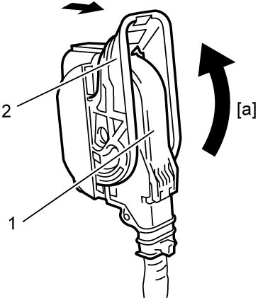
2)Disconnect ESP® control module connector (1) by pulling up the lock lever (2).

| [a]: | Pull up to disconnect |
3)For D16AA model, remove degassing tank, if necessary. 
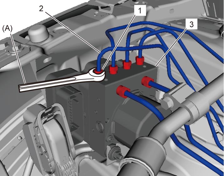
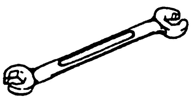
4)Loosen flare nuts (1) using special tool and disconnect brake pipes (2) from ESP® hydraulic unit / control module assembly (3).
NOTE:
Put bleeder plug cap or the like onto pipe to prevent fluid from spilling.
5)Remove or loosen ESP® hydraulic unit / control module assembly nuts (1) and remove ESP® hydraulic unit / control module assembly (3) from actuator bracket (2).
NOTE:
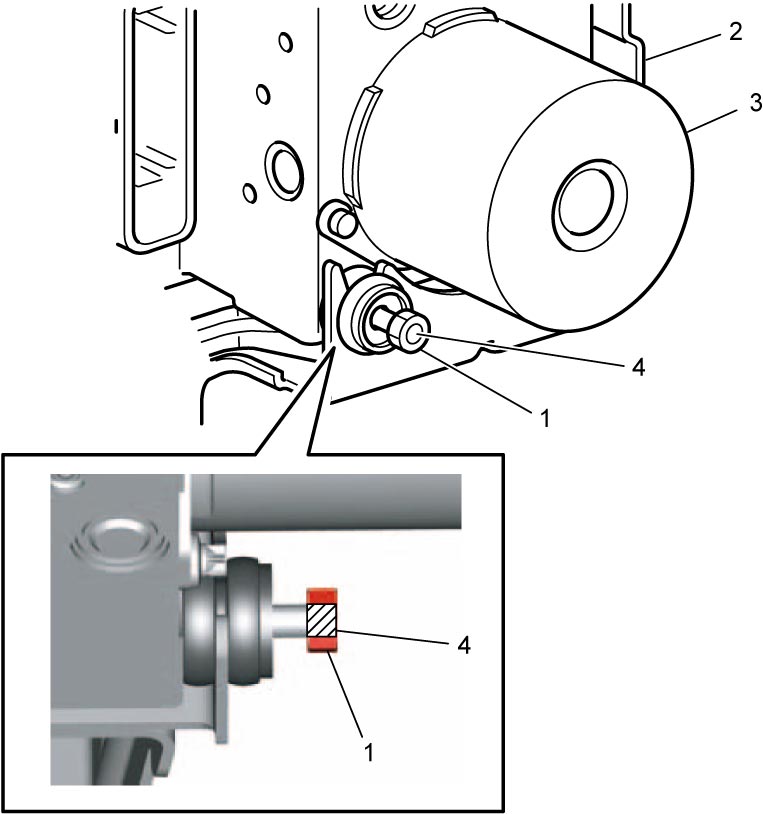
If ESP® hydraulic unit / control module assembly nuts are not removed, loosen each nut to the end of screw (4) as shown in figure.
Installation
Reverse removal procedure noting the following points.
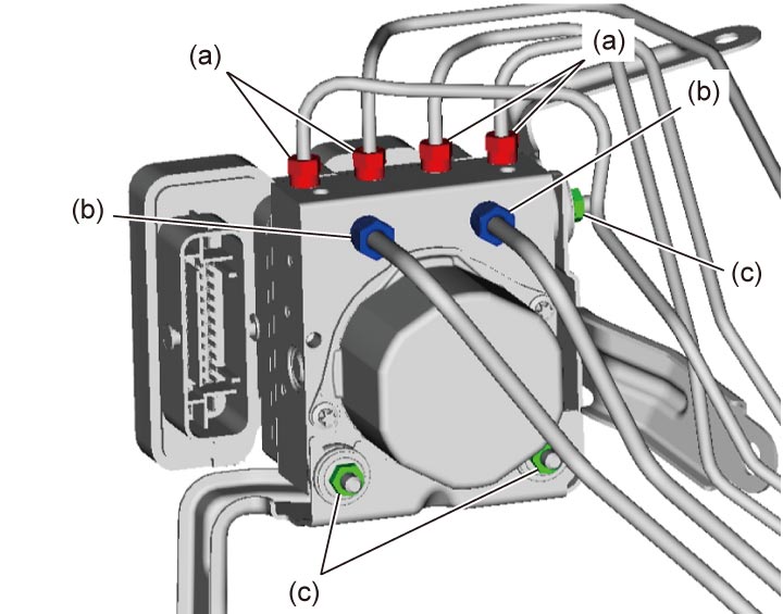
•Tighten brake pipe flare nuts to specified torque. Also tighten ESP® hydraulic unit / control module assembly nuts to specified torque.
Brake pipe flare nut (M12) (b): 19 N·m (1.9 kgf-m, 14.0 lbf-ft)
ESP® hydraulic unit / control module assembly nut (c): 9.0 N·m (0.92 kgf-m, 7.0 lbf-ft)
 •Bleed brake system.
•Check for leakage of brake fluid and perform ESP® hydraulic unit operation check.
Tightening torque
Brake pipe flare nut (M10) (a): 16 N·m (1.6 kgf-m, 12.0 lbf-ft)Brake pipe flare nut (M12) (b): 19 N·m (1.9 kgf-m, 14.0 lbf-ft)
ESP® hydraulic unit / control module assembly nut (c): 9.0 N·m (0.92 kgf-m, 7.0 lbf-ft)
•Check for leakage of brake fluid and perform ESP® hydraulic unit operation check.