Electronic Shift Control System Circuit Diagram
Precautions: Precautions for Diagnosing Trouble · Precautions for Disassembly and Reassembly · Precautions for Transmission / Transaxle · General safety (00)
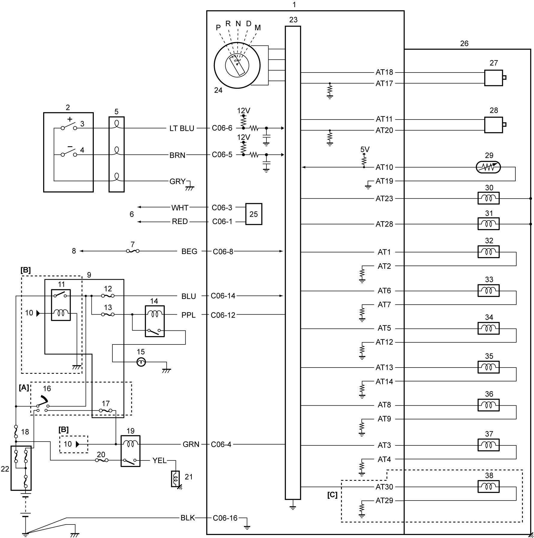
| [A]: | Ignition switch model | 12. | “IG1 SIG” fuse | 26. | A/T |
| [B]: | Keyless push start model | 13. | “BACK” fuse | 27. | Input shaft speed sensor |
| [C]: | ENG A-STOP model | 14. | Back up light relay | 28. | Output shaft speed sensor |
| 1. | TCM | 15. | Back up light | 29. | ATF temperature sensor |
| 2. | Shift paddles | 16. | Ignition switch | 30. | Shift solenoid valve “A” |
| 3. | Paddle-up switch | 17. | “ST SIG” fuse | 31. | Shift solenoid valve “B” |
| 4. | Paddle-down switch | 18. | “IGN” fuse | 32. | TCC solenoid valve |
| 5. | Contact coil | 19. | Starting motor control relay | 33. | Line pressure control solenoid valve |
| 6. | To other control modules and sensor connected by CAN | 20. | “ST” fuse | 34. | Pressure control solenoid valve “C” |
| 7. | “T/M5” fuse (ENG A-STOP model) or “T/M1” fuse (Non-ENG A-STOP model) | 21. | Starting motor | 35. | Pressure control solenoid valve “A” |
| 8. | To DC/DC converter (ENG A-STOP model) or battery (Non-ENG A-STOP model) | 22. | Main fuse box | 36. | Pressure control solenoid valve “B” |
| 9. | J/B | 23. | CPU | 37. | Pressure control solenoid valve “D” |
| 10. | To keyless start control module | 24. | Transmission range sensor | 38. | Electro magnetic oil pump solenoid valve |
| 11. | IG1 relay | 25. | CAN driver |
Terminal Arrangement of TCM Connector and Solenoid Harness Connector
NOTE:
For circuit name and terminal voltage, refer to Inspection of TCM and Its Circuits.
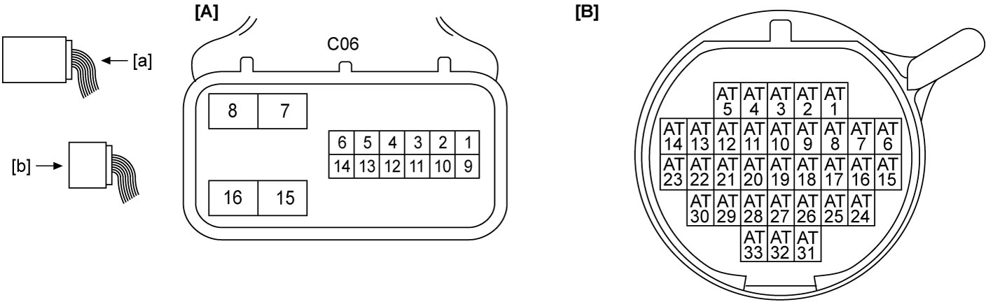
| [A]: | TCM connector (View: [a]) | [B]: | Solenoid harness connector (View: [b]) |