Select Lever Assembly Disassembly and Reassembly
Precautions: Precautions for Diagnosing Trouble · Precautions for Disassembly and Reassembly · Precautions for Transmission / Transaxle · General safety (00)
Disassembly
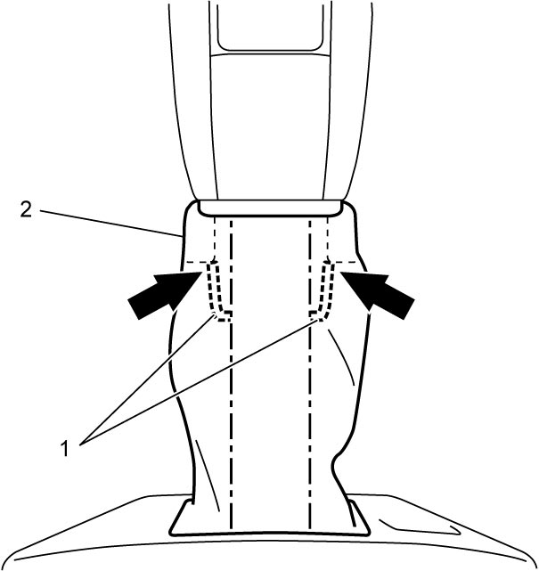
1)While pushing locks (1), pull down select lever boot (2).

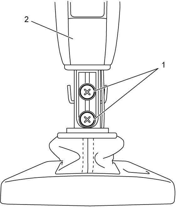
2)Remove select lever knob screws (1) and pull out select lever knob assembly (2).
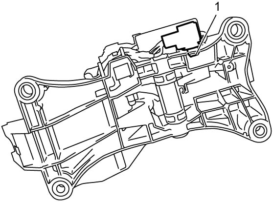
3)Disconnect select lever connector clamp (1).
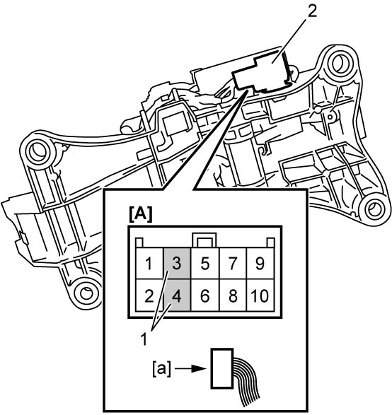
4)Disconnect select lever illumination light terminals (1) from select lever connector (2) in positions shown in figure according to the following procedure.
NOTICE:
•Connector claws may be deformed if terminals are disconnected improperly from connector, causing terminals coming off the connector during connector assembly.
Be careful not to deform connector claws.
•Terminals may be deformed if they are disconnected improperly from connector, causing poor contact.
Be careful not to deform terminals.
Be careful not to deform connector claws.
•Terminals may be deformed if they are disconnected improperly from connector, causing poor contact.
Be careful not to deform terminals.
| [A]: | Select lever connector (View: [a]) |
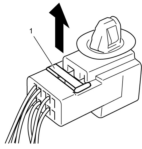
a)Pull up terminal lock (1) approx. 1.0 mm (0.039 in.).
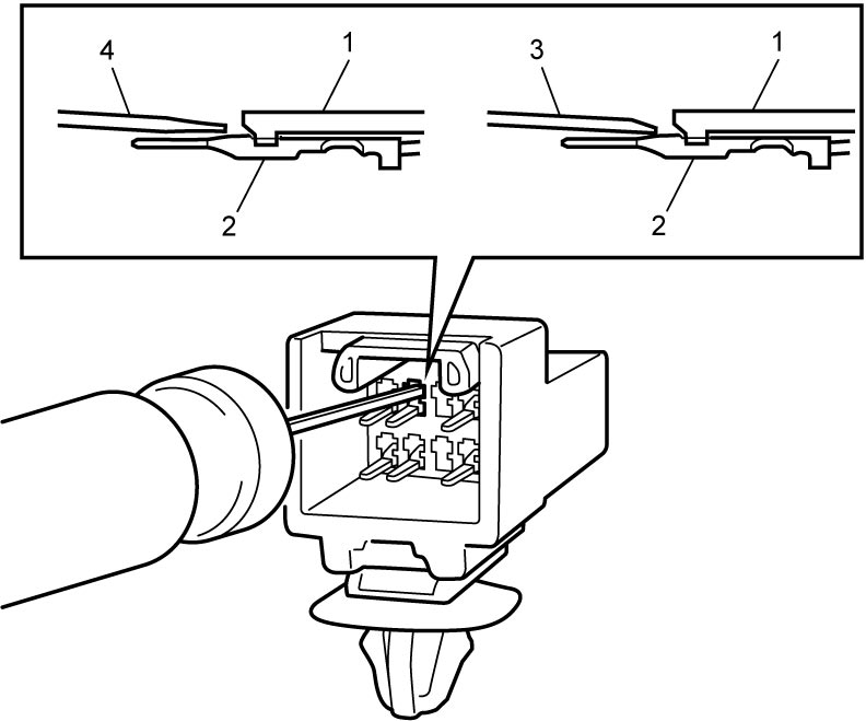
b)Insert terminal release tool (3) or flat-bladed precision screwdriver (4) between connector claw (1) and terminal (2), and then lift up connector claw slightly to release terminal.
NOTE:
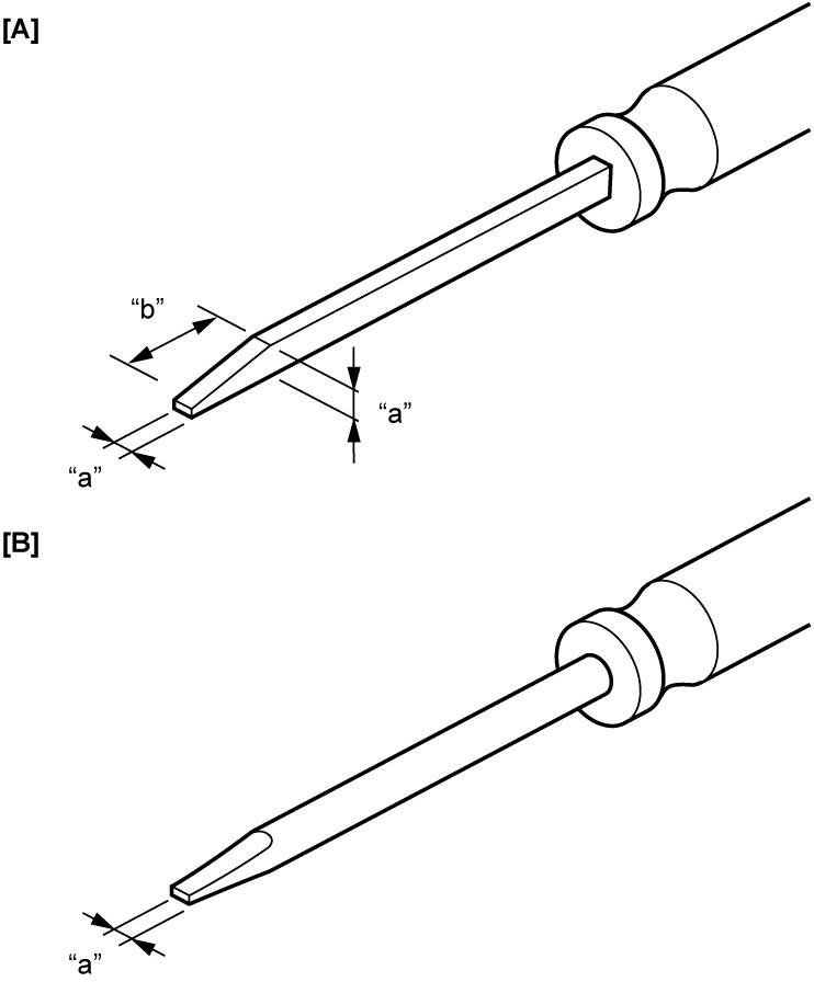
Use the tool shown in figure below.
| [A]: | Terminal release tool | “a”: | Approx. 1.0 mm (0.039 in.) |
| [B]: | Flat-bladed precision screwdriver | “b”: | Approx. 2.5 mm (0.098 in.) |
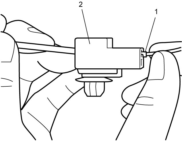
c)Pull wiring to remove terminal (1) from connector (2).
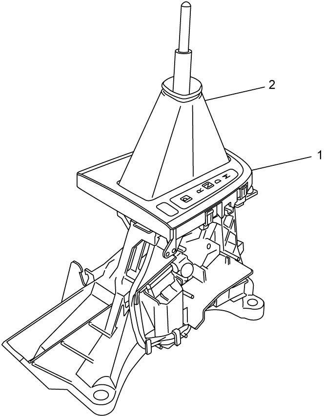
5)Remove select lever indicator (1) with select lever boot (2).
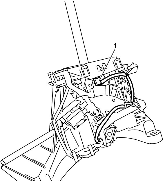
6)Remove select lever illumination light assembly (1).
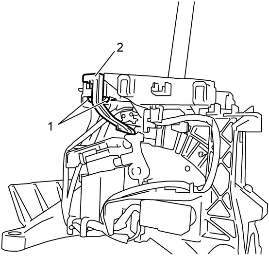
7)Release claws (1), and then remove shift lock solenoid release plate (2) and spring.
Reassembly
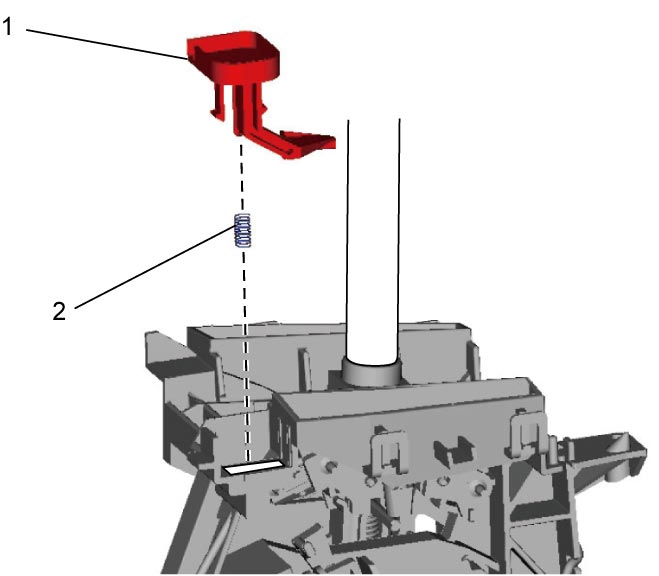
1)Push shift lock solenoid release plate (1) along with spring (2) until claws lock in place to install them.
2)Check that select lever can be shifted from P range to other ranges when shift lock solenoid release plate is pushed.
3)Install select lever illumination light assembly (1) and fix harness to select lever as shown in figure.
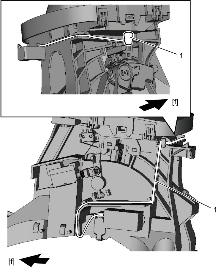
LHD model
RHD model
| [f]: | Vehicle forward |
4)Connect select lever illumination light terminals (1) to select lever connector (2) at positions shown in figure according to the following procedure.
NOTE:
Polarity of select lever illumination light terminals does not affect their performance. Therefore, connection of select lever illumination light terminals 3, 4 can be either positive or negative.
| [A]: | Select lever connector (View: [a]) |
a)Align protrusions (2) on terminals with slots (1) in connector, and then push terminals into connector until they click into place.
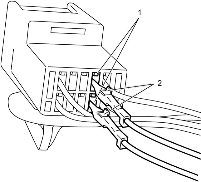
b)Pull wirings slightly to check that terminals are firmly locked in place.
c)Push terminal lock (1) into connector until it is flush with connector surface.
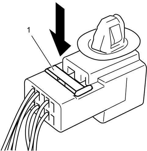
5)Connect select lever connector clamp (1).
6)Install select lever indicator (1), select lever boot (2) and select lever knob assembly (3) all together.
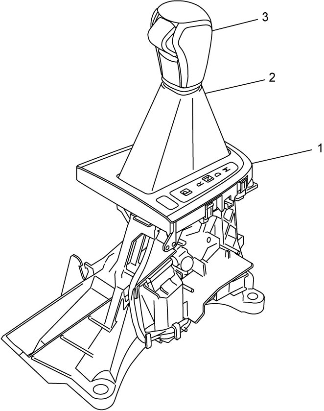
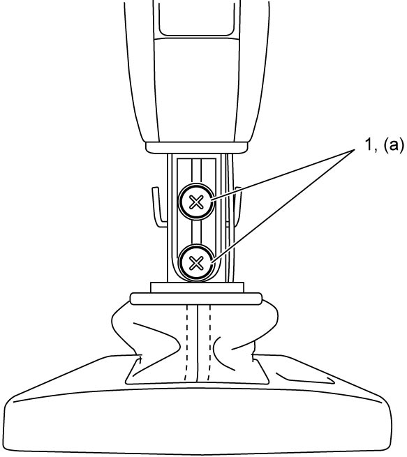
7)Tighten select lever knob screws (1) to specified torque.
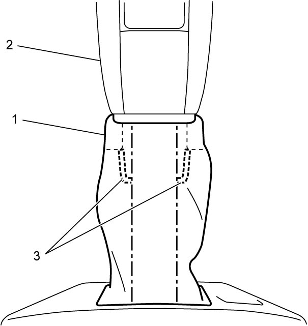
8)Pull up select lever boot (1) to lower end of select lever knob assembly (2) over the locks (3).
9)After installing select lever assembly, adjust select cable. 