P/S System Diagram
Precautions: Precautions for Diagnosing Trouble · Precautions for Steering · General safety (00)
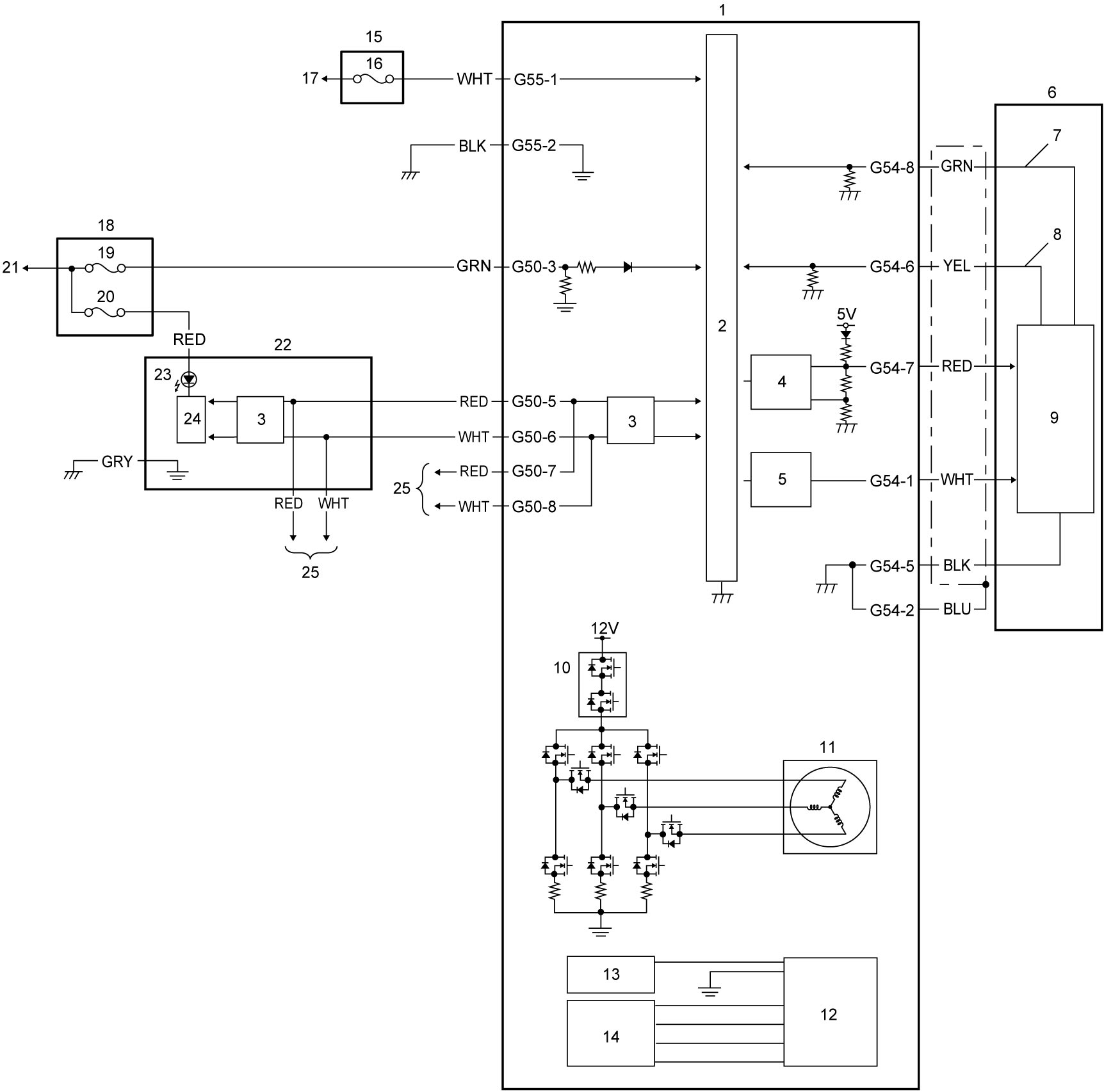
| 1. | P/S control module / motor assembly | 10. | Fail-safe relay | 19. | “IG1 SIG” fuse |
| 2. | CPU | 11. | P/S motor | 20. | “MTR” fuse |
| 3. | CAN driver | 12. | Rotation angle sensor | 21. | To ignition power supply |
| 4. | 9 V regulator | 13. | Rotation angle sensor exciter circuit | 22. | Combination meter |
| 5. | 3 V reference power supply | 14. | Rotation angle sensor signal receive circuit | 23. | P/S warning light |
| 6. | Torque sensor | 15. | Main fuse box | 24. | Meter driver |
| 7. | Torque sensor (main) circuit | 16. | “P/S” fuse | 25. | To other control modules by CAN |
| 8. | Torque sensor (sub) circuit | 17. | To continuous power supply | ||
| 9. | Torque sensor amplifier | 18. | J/B |
Terminal Arrangement of P/S Control Module Connector (Viewed from Harness Side)
NOTE:
For circuit name and terminal voltage, refer toInspection of P/S Control Module and Its Circuits.

| [A]: | P/S control module connector (View: [a]) | 1. | P/S control module |