P/S Warning Light Does Not Come ON with Ignition “ON” before Engine Starts
Precautions: Precautions for Diagnosing Trouble · Precautions for Steering · General safety (00)
Circuit Diagram
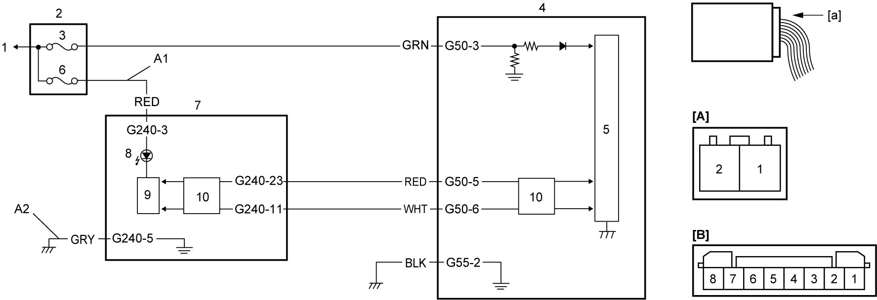
| [A]: | P/S control module connector “G55” (View: [a]) | 2. | J/B | 7. | Combination meter |
| [B]: | P/S control module connector “G50” (View: [a]) | 3. | “IG1 SIG” fuse | 8. | P/S warning light |
| A1: | Combination meter power supply circuit | 4. | P/S control module / motor assembly | 9. | Meter driver |
| A2: | Combination meter ground circuit | 5. | CPU | 10. | CAN driver |
| 1. | To ignition power supply | 6. | “MTR” fuse |
Troubleshooting
| Step | Action | Yes | No |
|---|---|---|---|
| 1 |
P/S warning light check
1)Set ignition “ON”.
Do other warning lights come ON?
|
Go to Step 2.
|
Go to Step 4.
|
| 2 |
DTC check
1)Connect scan tool to DLC with ignition “OFF”.
2)When ignition is “ON”, check DTC.
Is DTC U0073 or U0155 detected?
|
•M16A model: Refer to CAN DTC (Lost Communication and Communication Bus Off) Table:M16A Model.
•K14C model: Refer to CAN DTC (Lost Communication and Communication Bus Off) Table:K14C Model. •D16AA model: Refer to CAN DTC (Lost Communication and Communication Bus Off) Table:D16AA Model. |
Go to Step 3.
|
| 3 |
Combination meter check
1)Replace combination meter.

2)Set ignition “ON”.
Does P/S warning light stay OFF?
|
Replace steering column assembly.
|
End.
|
| 4 |
Fuse check
Is circuit fuse for combination meter in good condition?
|
Go to Step 5.
|
Replace fuse and check for short circuit to ground.
|
| 5 |
CAN communication circuit check
1)Check CAN communication circuit between combination meter and P/S control module.
•M16A model:
•K14C model: •D16AA model: Is CAN communication circuit in good condition?
|
Go to Step 6.
|
Repair or replace.
|
| 6 |
Combination meter power supply circuit check
1)Remove combination meter with ignition “OFF”.
2)Check for proper connection to combination meter connector.
3)If check result is OK, set ignition “ON”.
4)Check voltage between “G240-3” terminal and “G240-5” terminal is battery voltage.
Is check result OK?
|
Replace combination meter and recheck DTC.
|
Go to Step 7.
|
| 7 |
Combination meter ground circuit check
1)Set ignition “OFF”.
2)Check resistance between “G240-5” terminal and ground is 1 Ω or less.
Is check result OK?
|
Repair or replace “A1” circuit.
|
Repair or replace “A2” circuit.
|