Steering Column Removal and Installation
Precautions: Precautions for Steering Wheel and Column · Precautions for Steering · General safety (00)
NOTICE:
The steering column assembly can be easily damaged during and after removal.
To avoid damaging the steering column assembly, take the following precautions when removing it and when setting it down after removal:
•Do not release tilt lever with steering column nuts loosened or steering column removed from vehicle. Doing so may increase operating force for telescopic or tilt motion.
•The impact energy absorbing function of the steering column assembly may be impaired if the steering column assembly receives an excessively large force.
Be careful not to strongly impact the steering column assembly when removing and installing it.
•Never drop the steering column assembly on its end. This could collapse the steering shaft or loosen capsules that maintain the design length of the column.
•Do not lean the steering column assembly against something. This could cause it to bend or deform.
•Do not loosen the steering column nuts when the steering lower shaft is still installed. This could cause damage to the shaft joint bearing.
•The impact energy absorbing function of the steering column assembly may be impaired if the steering column assembly receives an excessively large force.
Be careful not to strongly impact the steering column assembly when removing and installing it.
•Never drop the steering column assembly on its end. This could collapse the steering shaft or loosen capsules that maintain the design length of the column.
•Do not lean the steering column assembly against something. This could cause it to bend or deform.
•Do not loosen the steering column nuts when the steering lower shaft is still installed. This could cause damage to the shaft joint bearing.
Removal
1)Remove steering joint cover. 
2)Remove instrument panel undercover.
3)Remove steering lower shaft.
4)Remove steering wheel.
5)Remove contact coil assembly.
6)For ignition switch model, remove immobilizer control module from steering lock.
7)Remove lighting switch and wiper switch.
•Lighting switch:
•Wiper switch:
•Wiper switch:
8)Remove steering column hole cover.
9)Remove knee air bag (inflator) module (if equipped).
10)For A/T model with ignition switch, disconnect key interlock cable.
11)Remove combination meter.
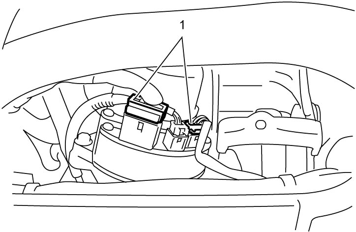
12)Disconnect P/S control module connectors (1).

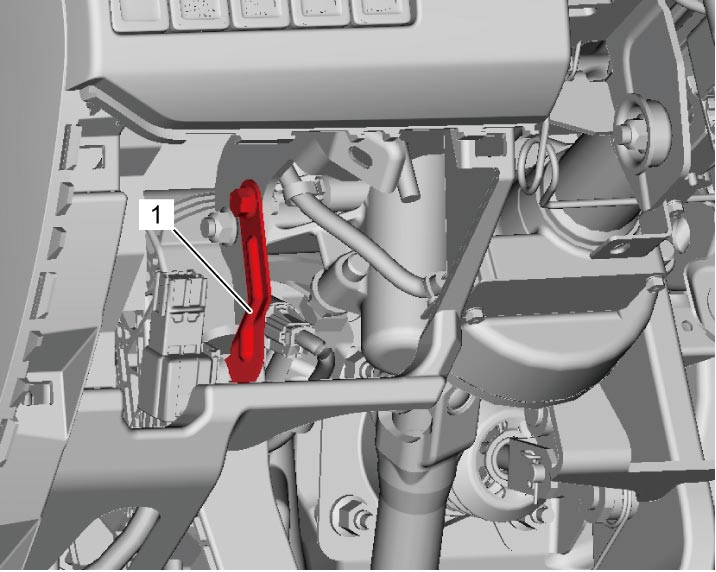
13)For LHD model, remove harness bracket (1).
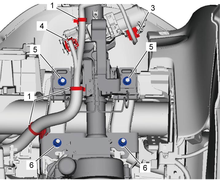
14)Detach steering column harness clamps (1).
15)For keyless push start model, disconnect steering lock connector (2).
For ignition switch model, disconnect both key reminder switch connector (3) and ignition switch connector (4).
For ignition switch model, disconnect both key reminder switch connector (3) and ignition switch connector (4).
16)Remove steering column upper nuts (5) and then steering column lower nuts (6).
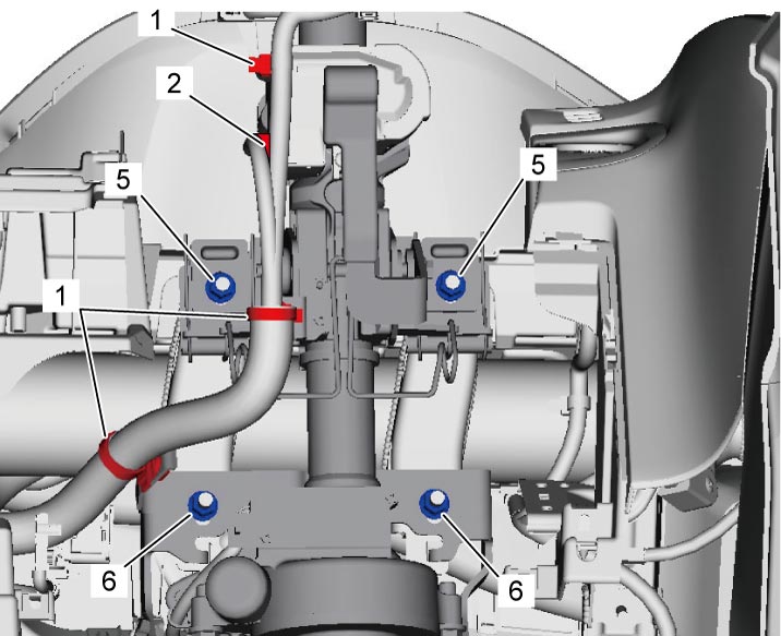
Keyless push start model
Ignition switch model
17)Remove steering column.
Installation
NOTICE:
Tightening the fasteners in the wrong order may cause damage to the shaft joint bearing.
Tighten the steering column nuts in the order given before installing the steering lower shaft.
1)Check that vehicle’s front wheels are in straight ahead position.
2)Install steering column.
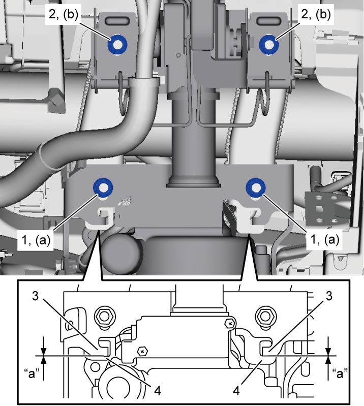
3)Tighten steering column lower nuts (1) on lower side and then steering column upper nuts (2) on upper side to specified torque.
Steering column upper nut (b): 14 N·m (1.4 kgf-m, 10.5 lbf-ft)
NOTE:
•When installing steering column, check that clearance “a” between column lower bracket (3) and column hanger bracket (4) is 0 (zero).
•After installing steering column, check that telescopic and tilt functions operate smoothly when lever is released and the functions are securely fixed when lever is locked.
•After installing steering column, check that telescopic and tilt functions operate smoothly when lever is released and the functions are securely fixed when lever is locked.
Tightening torque
Steering column lower nut (a): 14 N·m (1.4 kgf-m, 10.5 lbf-ft)Steering column upper nut (b): 14 N·m (1.4 kgf-m, 10.5 lbf-ft)
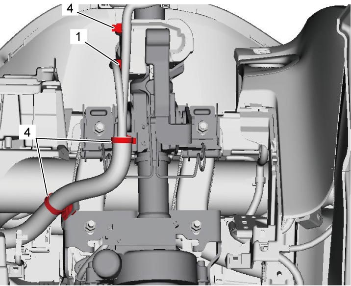
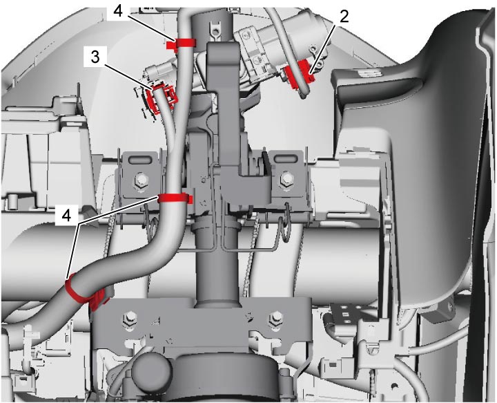
4)For keyless push start model, connect steering lock connector (1).
For ignition switch model, connect both key reminder switch connector (2) and ignition switch connector (3).
For ignition switch model, connect both key reminder switch connector (2) and ignition switch connector (3).
5)Attach steering column harness clamps (4) in place.
Keyless push start model
Ignition switch model
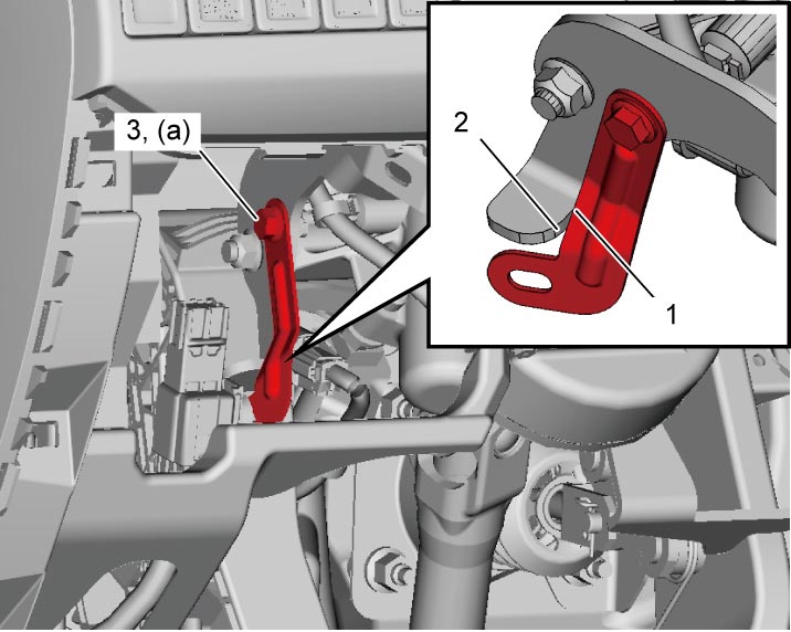
6)Put harness bracket so that the edge (1) is in contact with column lower bracket edge (2) as shown in figure and tighten harness bracket bolt (3) to specified torque.
7)Connect P/S control module connectors (1).
8)Install combination meter.
9)For A/T model with ignition switch, connect key interlock cable.
10)Install knee air bag (inflator) module (if equipped).
11)Install steering column hole cover.
12)Install lighting switch and wiper switch.
•Lighting switch:
•Wiper switch:
•Wiper switch:
13)For ignition switch model, install immobilizer control module to steering lock.
14)Install contact coil assembly.
15)Install steering wheel.
16)Install steering lower shaft.
17)Install instrument panel undercover.
18)Install steering joint cover.