DTC B1511-L / B1512-L / B1530-L
Precautions: Precautions for Diagnosing Trouble · General safety (00)
DTC Detecting Condition and Trouble Area
| DTC detecting condition | Trouble area |
|---|---|
|
B1511-L: Temperature Control Actuator (Position Sensor) and/or Its Circuit Malfunction Signal voltage of position sensor in temperature control actuator is lower than specified value (0.1 V) for specified time continuously. |
•Temperature control actuator circuit
•Temperature control actuator •HVAC control module |
|
B1512-L: Air Flow Control Actuator (Position Sensor) and/or Its Circuit Malfunction Signal voltage of position sensor in air flow control actuator is lower than specified value (0.1 V) for specified time continuously. |
•Air flow control actuator circuit
•Air flow control actuator •HVAC control module |
|
B1530-L: Air Intake Control Actuator (Position Sensor) and/or Its Circuit Malfunction Signal voltage of position sensor in air intake control actuator is lower than specified value (0.1 V) for specified time continuously. |
•Air intake control actuator circuit
•Air intake control actuator •HVAC control module |
Circuit Diagram
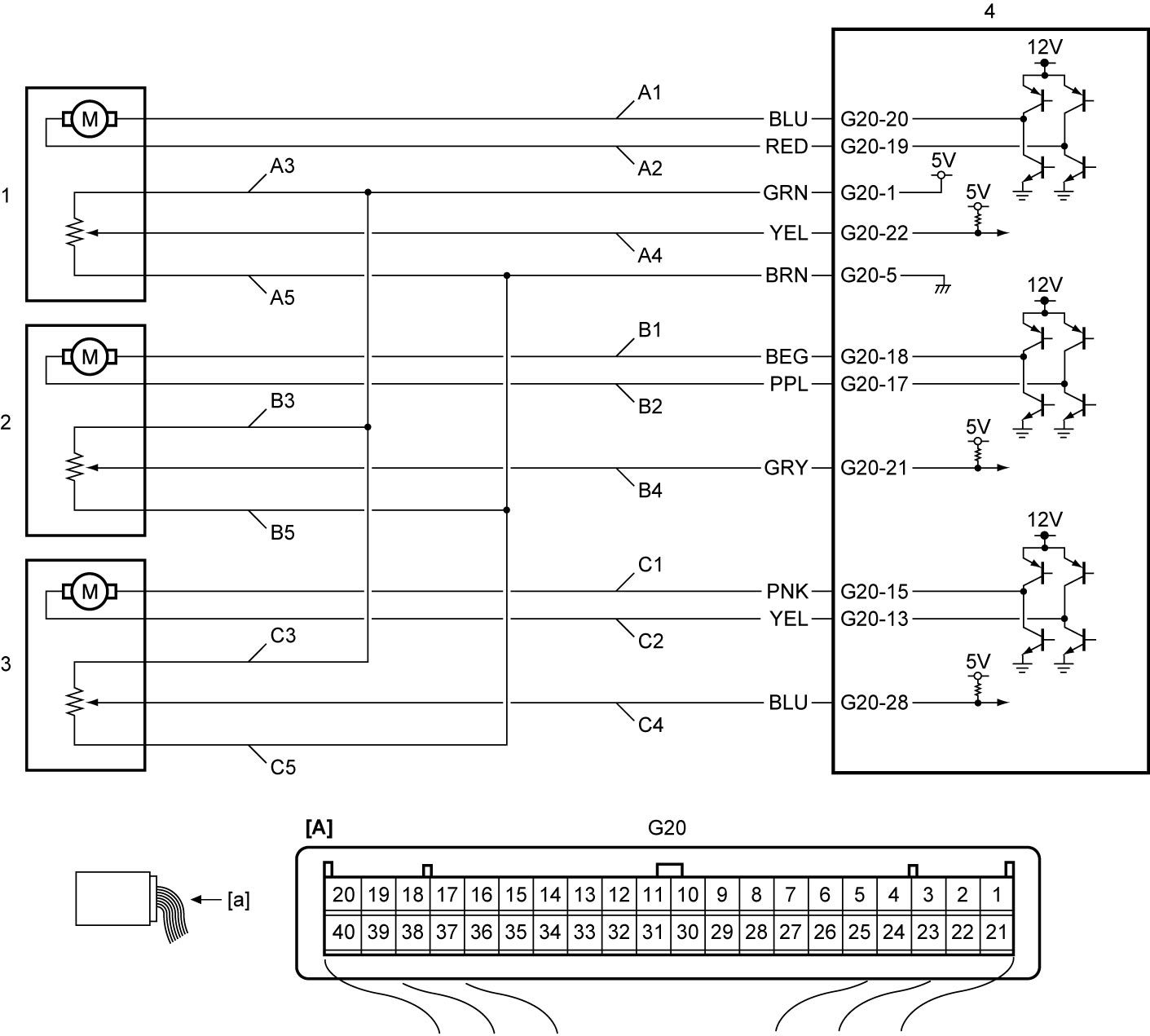
| [A]: | HVAC control module connector (View: [a]) | B2. | Air flow control actuator circuit (“FACE”) | C4. | Air intake control actuator position sensor signal circuit |
| A1. | Temperature control actuator circuit (“COOL”) | B3. | Air flow control actuator position sensor power supply circuit | C5. | Air intake control actuator position sensor ground circuit |
| A2. | Temperature control actuator circuit (“HOT”) | B4. | Air flow control actuator position sensor signal circuit | 1. | Temperature control actuator |
| A3. | Temperature control actuator position sensor power supply circuit | B5. | Air flow control actuator position sensor ground circuit | 2. | Air flow control actuator |
| A4. | Temperature control actuator position sensor signal circuit | C1. | Air intake control actuator circuit (“FRE”) | 3. | Air intake control actuator |
| A5. | Temperature control actuator position sensor ground circuit | C2. | Air intake control actuator circuit (“REC”) | 4. | HVAC control module |
| B1. | Air flow control actuator circuit (“DEF”) | C3. | Air intake control actuator position sensor power supply circuit |
DTC Confirmation Procedure
1)Start engine and operate A/C system.
DTC Troubleshooting
NOTE:
•The following flow shows “DTC B1511-L: Temperature Control Actuator (Position Sensor) and/or Its Circuit Malfunction”.
•Check “DTC B1512-L / B1530-L” in the same manner as “DTC B1511-L” referring to the following table.
•Check “DTC B1512-L / B1530-L” in the same manner as “DTC B1511-L” referring to the following table.
| DTC | Parameter | Circuit |
|---|---|---|
| B1512-L | Mode Pos Sensor | “A3” and “B4” circuit |
| B1530-L | R/F Pos Sensor | ”A3” and “C4” circuit |
| Step | Action | Yes | No |
|---|---|---|---|
| 1 |
Scan tool parameter check
1)Check “Air Mix Pos Sen” using “Data list” mode on SUZUKI scan tool.

Is voltage below 0.1 V?
|
Go to Step 2.
|
Intermittent trouble.
|
| 2 |
Temperature control actuator position sensor signal circuit check
1)Disconnect temperature control actuator connector.
2)Check “Air Mix Pos Sen” using “Data list” mode on SUZUKI scan tool.
Is voltage below 0.1 V?
|
Go to Step 3.
|
Replace temperature control actuator.
|
| 3 |
Temperature control actuator position sensor signal circuit check
1)Set ignition “ON”.
2)Measure voltage between “A3” circuit terminal of temperature control actuator connector and ground.
Is voltage 5 V?
|
Go to Step 5.
|
Go to Step 4.
|
| 4 |
Temperature control actuator position sensor signal circuit check
1)Disconnect “G20” connector.
2)Check the following points.
•Resistance of “A3” circuit: less than 1 Ω
•Resistance of “A3” circuit between temperature control actuator and ground: infinity Are resistances as specified?
|
Replace HVAC control module and recheck DTC.
|
Replace instrument panel harness.
|
| 5 |
Temperature control actuator position sensor signal circuit check
1)Check that resistance between the “A3” and “A4” circuit terminals and ground is infinity.
Is resistance as specified?
|
Replace HVAC control module and recheck DTC.
|
Replace instrument panel harness.
|