DTC B1513 / B1514 / B1531
Precautions: Precautions for Diagnosing Trouble · General safety (00)
DTC Detecting Condition and Trouble Area
| DTC detecting condition | Trouble area |
|---|---|
|
B1513: Temperature Control Actuator (Motor) and/or Its Circuit Malfunction Difference between target opening and actual opening is more than specified value even though temperature control actuator has operated for specified time. |
•Temperature control actuator circuit
•Temperature control actuator •HVAC control module |
|
B1514: Air Flow Control Actuator (Motor) and/or Its Circuit Malfunction Difference between target opening and actual opening is more than specified value even though air flow control actuator has operated for specified time. |
•Air flow control actuator circuit
•Air flow control actuator •HVAC control module |
|
B1531: Air Intake Control Actuator and/or Its Circuit Malfunction Difference between target opening and actual opening is more than specified value even though air intake control actuator has operated for specified time. |
•Air intake control actuator circuit
•Air intake control actuator •HVAC control module |
Circuit Diagram
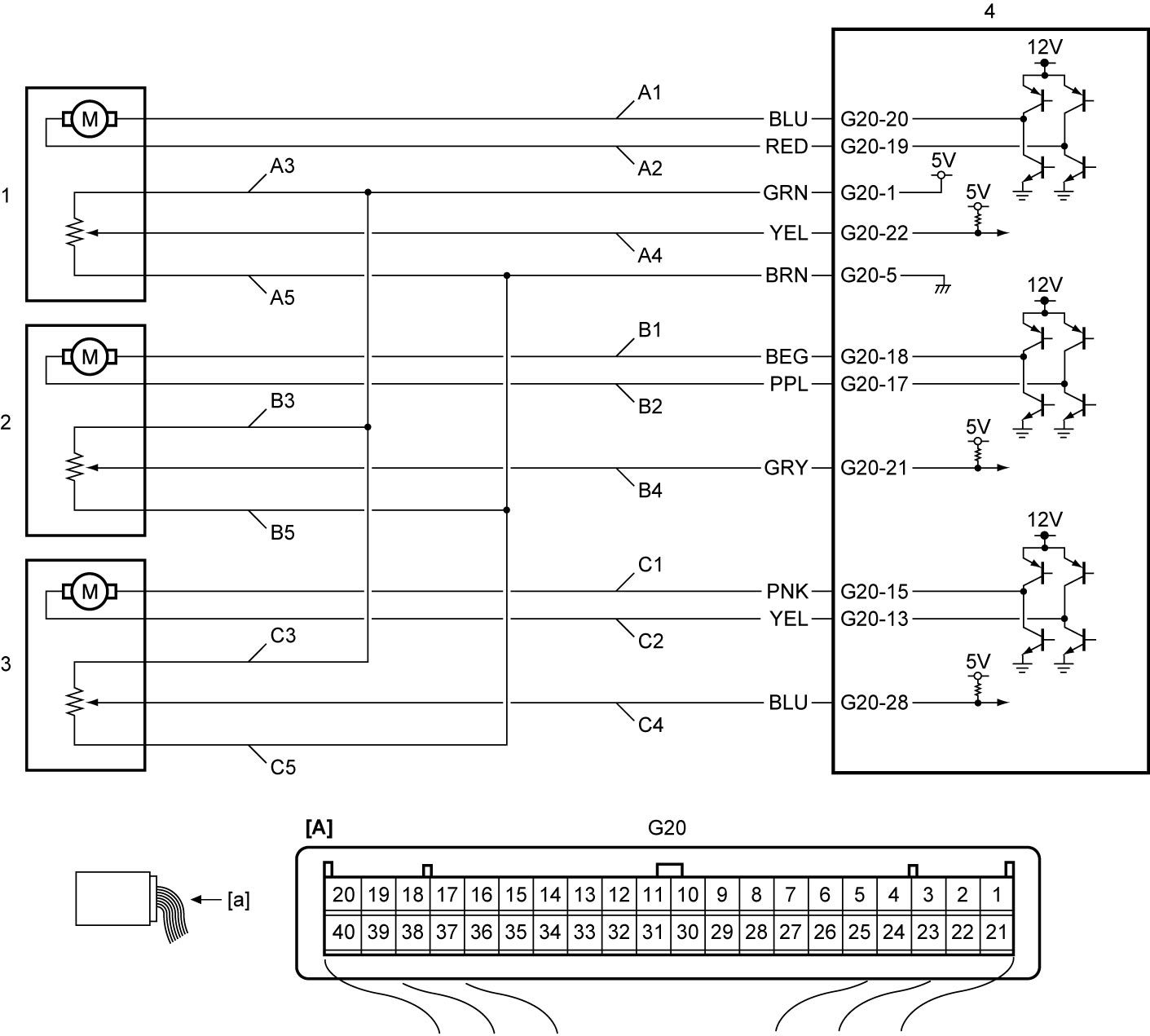
| [A]: | HVAC control module connector (View: [a]) | B2. | Air flow control actuator circuit (“FACE”) | C4. | Air intake control actuator position sensor signal circuit |
| A1. | Temperature control actuator circuit (“COOL”) | B3. | Air flow control actuator position sensor power supply circuit | C5. | Air intake control actuator position sensor ground circuit |
| A2. | Temperature control actuator circuit (“HOT”) | B4. | Air flow control actuator position sensor signal circuit | 1. | Temperature control actuator |
| A3. | Temperature control actuator position sensor power supply circuit | B5. | Air flow control actuator position sensor ground circuit | 2. | Air flow control actuator |
| A4. | Temperature control actuator position sensor signal circuit | C1. | Air intake control actuator circuit (“FRE”) | 3. | Air intake control actuator |
| A5. | Temperature control actuator position sensor ground circuit | C2. | Air intake control actuator circuit (“REC”) | 4. | HVAC control module |
| B1. | Air flow control actuator circuit (“DEF”) | C3. | Air intake control actuator position sensor power supply circuit |
DTC Confirmation Procedure
B1513
1)Start engine and operate A/C system.
2)Change position of temperature selector from “LO” to “HI” gradually.
B1514
1)Start engine and operate A/C system.
2)Push “MODE” switch to change position from “FACE” to “DEF”.
B1531
1)Start engine and operate A/C system.
2)Push air intake switch to change position from “REC” to “FRE”.
DTC Troubleshooting
NOTE:
•When DTC B1513, B1514 and/or B1531 is detected, check that there is any obstruction in opening range of actuator linkage.
•The following flow shows “DTC B1513: Temperature Control Actuator and/or Its Circuit Malfunction”.
•Check “DTC B1514 / B1531” in the same manner as “DTC B1513” referring to the following table.
•The following flow shows “DTC B1513: Temperature Control Actuator and/or Its Circuit Malfunction”.
•Check “DTC B1514 / B1531” in the same manner as “DTC B1513” referring to the following table.
| DTC | Parameter | Circuit |
|---|---|---|
| B1514 | Mode Pos Sensor | “B1” and “B2” circuit |
| B1531 | R/F Pos Sensor | “C1” and “C2” circuit |
| Step | Action | Yes | No |
|---|---|---|---|
| 1 |
Scan tool parameter check
1)Check “Air Mix Pos Sen” using “Data list” mode on SUZUKI scan tool.

Is check result OK?
|
Intermittent trouble.
|
Go to Step 2.
|
| 2 |
Temperature control actuator circuit check
1)Disconnect “G20” and temperature control actuator connectors.
2)Check the following points.
•Resistance of “A1” and “A2” circuits: less than 1 Ω
•Resistance of “A1” and “A2” circuits between temperature control actuator and ground: infinity Are resistances as specified?
|
Go to Step 3.
|
Replace instrument panel harness.
|
| 3 |
Temperature control actuator check
1)Check temperature control actuator.
Is actuator in good condition?
|
Replace HVAC control module and recheck DTC.
|
Replace temperature control actuator.
|