DTC B1957 / B1958
Precautions: Precautions for Headlight Auto Leveling System Service · Precautions for Body, Cab and Accessories · General safety (00)
DTC Detecting Condition and Trouble Area
| DTC detecting condition | Trouble area |
|---|---|
|
B1957: Right Side Headlight Control Circuit / Open Right side headlight unit diagnosis signal circuit voltage is higher than 1.5 V for specified time. |
•Headlight unit (R) and/or its circuit
•Headlight LO relay •Headlight auto leveling control module |
|
B1958: Left Side Headlight Control Circuit / Open Left side headlight unit diagnosis signal circuit voltage is higher than 1.5 V for specified time. |
•Headlight unit (L) and/or its circuit
•Headlight LO relay •Headlight auto leveling control module |
Circuit Diagram
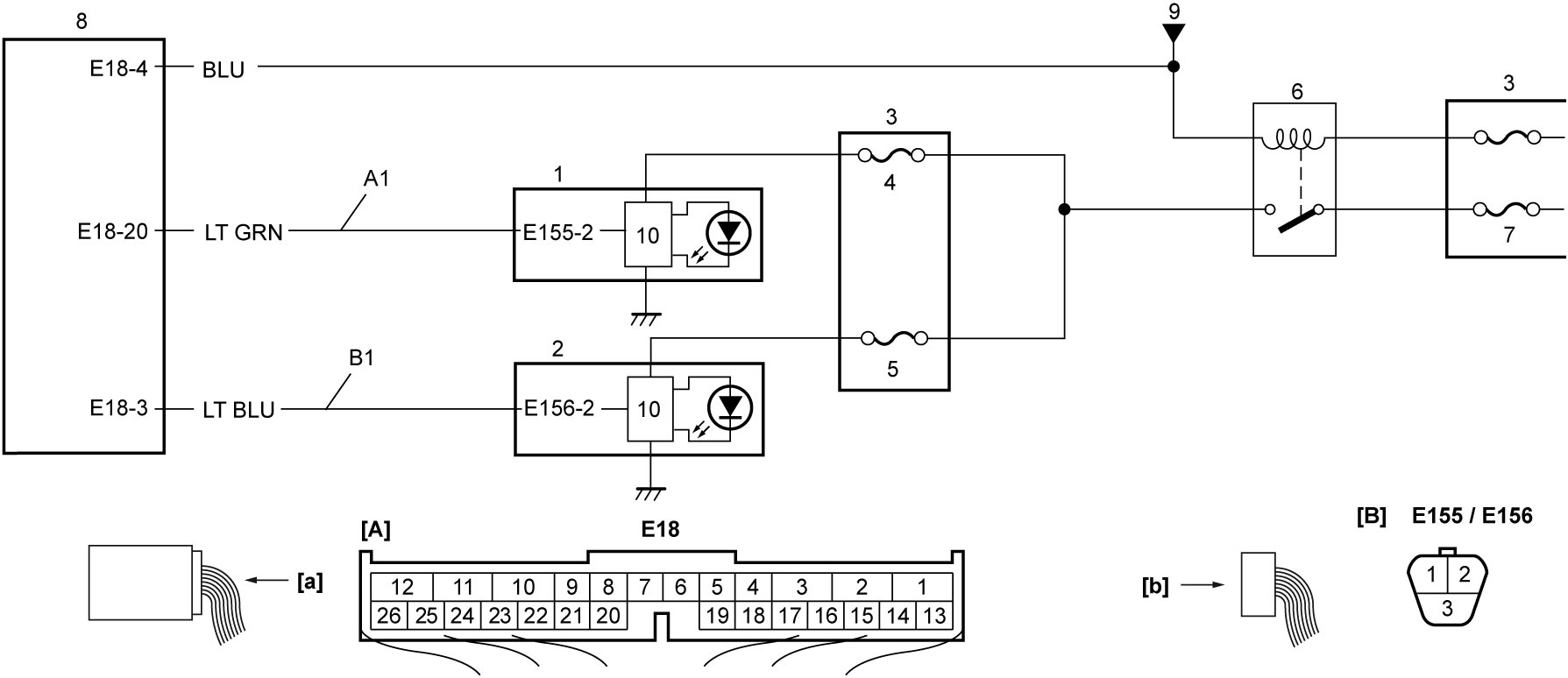
| [A]: | Headlight auto leveling control module connector (View: [a]) | 2. | Headlight unit (L) | 7. | “H/L” fuse |
| [B]: | Headlight unit connector (View: [b]) | 3. | Relay box No.1 | 8. | Headlight auto leveling control module |
| A1: | Headlight unit (R) diagnosis signal circuit | 4. | “H/L R” fuse | 9. | To lighting switch |
| B1: | Headlight unit (L) diagnosis signal circuit | 5. | “H/L L” fuse | 10. | LED control module |
| 1. | Headlight unit (R) | 6. | Headlight LO relay |
DTC Confirmation Procedure
1)Set ignition “ON”.
2)Turn lighting switch to headlight position.
DTC Troubleshooting
NOTE:
This DTC troubleshooting explains the inspection for B1957: Right Side Headlight Control Circuit / Open. For B1958, perform the same inspection.
| Step | Action | Yes | No |
|---|---|---|---|
| 1 |
DTC check
1)Clear DTC.

2)Set ignition “OFF”.
3)Perform “DTC Confirmation Procedure” and recheck DTC.
Is DTC B1957 still detected?
|
Go to Step 2.
|
Intermittent trouble.
|
| 2 |
Fuse check
1)Set ignition “OFF”.
2)Turn light switch to OFF position.
3)Check “H/L” fuse and “H/L R” fuse.
Is check result OK?
|
Go to Step 3.
|
Replace fuse and check for short circuit to ground.
|
| 3 |
Headlight LO relay check
1)Remove headlight LO relay.
2)Check headlight LO relay.
Is check result OK?
|
Go to Step 4.
|
Replace headlight LO relay.
|
| 4 |
Headlight unit diagnosis signal circuit check
1)Disconnect “E18” and “E155” connectors.
2)Check for proper terminal connections to “E18” and “E155” connectors.
3)If connections are OK, check “A1” circuit between “E18” connector and “E155” connector for open circuit, short to ground or short to power supply.
Is check result OK?
|
Go to Step 5.
|
Repair or replace defective harness and recheck DTC.
|
| 5 |
Headlight unit replacement
1)Replace headlight unit.
2)Clear DTC.
3)Set ignition “OFF”.
4)Perform “DTC Confirmation Procedure” and recheck DTC.
Is check result OK?
|
End.
|
Replace headlight auto leveling control module and recheck DTC.
|