Side Body Outside Dimensions
Precautions: Precautions for Body Structure · Precautions for Body, Cab and Accessories · General safety (00)
NOTE:
•Dimension with asterisk (*) shows distance to the same point on opposite side.
•In principle, body dimensions in the figure below are symmetrical. Adopt the dimension for the opposite side if the dimension is not mentioned in the figure below.
•The number with “ø” is circle diameter and measurement unit is “mm”.
•In principle, body dimensions in the figure below are symmetrical. Adopt the dimension for the opposite side if the dimension is not mentioned in the figure below.
•The number with “ø” is circle diameter and measurement unit is “mm”.
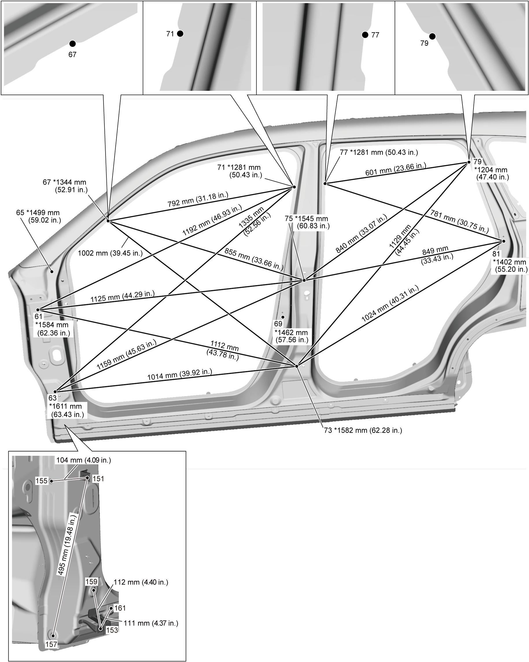
| Point | Position | ||
|---|---|---|---|
| 60 | Front door upper hinge installation hole (front side) | R | ø 14 hole center (weld nut M8) |
| 61 | ↑ | L | ↑ |
| 62 | Front door lower hinge installation hole (upper side) | R | ø 14 hole center (weld nut M8) |
| 63 | ↑ | L | ↑ |
| 64 | Front fender installation hole | R | ø 9 hole center (weld nut M6) |
| 65 | ↑ | L | ↑ |
| 66 | Side body outer panel (rear side of front-pillar) | R | Notch (concave upper side) |
| 67 | ↑ | L | ↑ |
| 68 | Front door switch installation hole | R | ø 17 hole center |
| 69 | ↑ | L | ↑ |
| 70 | Side body outer panel (front side of center-pillar) | R | Notch (concave upper side) |
| 71 | ↑ | L | ↑ |
| 72 | Rear door lower hinge installation hole (front side) | R | ø 14 hole center |
| 73 | ↑ | L | ↑ |
| 74 | Rear door upper hinge installation hole (lower side) | R | ø 14 hole center |
| 75 | ↑ | L | ↑ |
| 76 | Side body outer panel (rear side of center-pillar) | R | Notch (concave upper side) |
| 77 | ↑ | L | ↑ |
| 78 | Side body outer panel (front side of quarter-pillar) | R | Notch (concave upper side) |
| 79 | ↑ | L | ↑ |
| 80 | Rear door switch installation hole | R | ø 17 hole center |
| 81 | ↑ | L | ↑ |
| 150 | Front fender installation hole (front fender bracket) | R | ø 7 hole center (weld nut M6) |
| 151 | ↑ | L | ↑ |
| 152 | Front fender installation hole (front lower bracket) | R | ø 7 hole center (weld nut M6) |
| 153 | ↑ | L | ↑ |
| 154 | Cap installation hole (upper) | R | ø 17 hole center |
| 155 | ↑ | L | ↑ |
| 156 | Cap installation hole (lower) | R | ø 17 hole center |
| 157 | ↑ | L | ↑ |
| 158 | Cap installation hole (side) | R | ø 17 hole center |
| 159 | ↑ | L | ↑ |
| 160 | Side sill guard installation hole | R | ø 8.5 hole center |
| 161 | ↑ | L | ↑ |