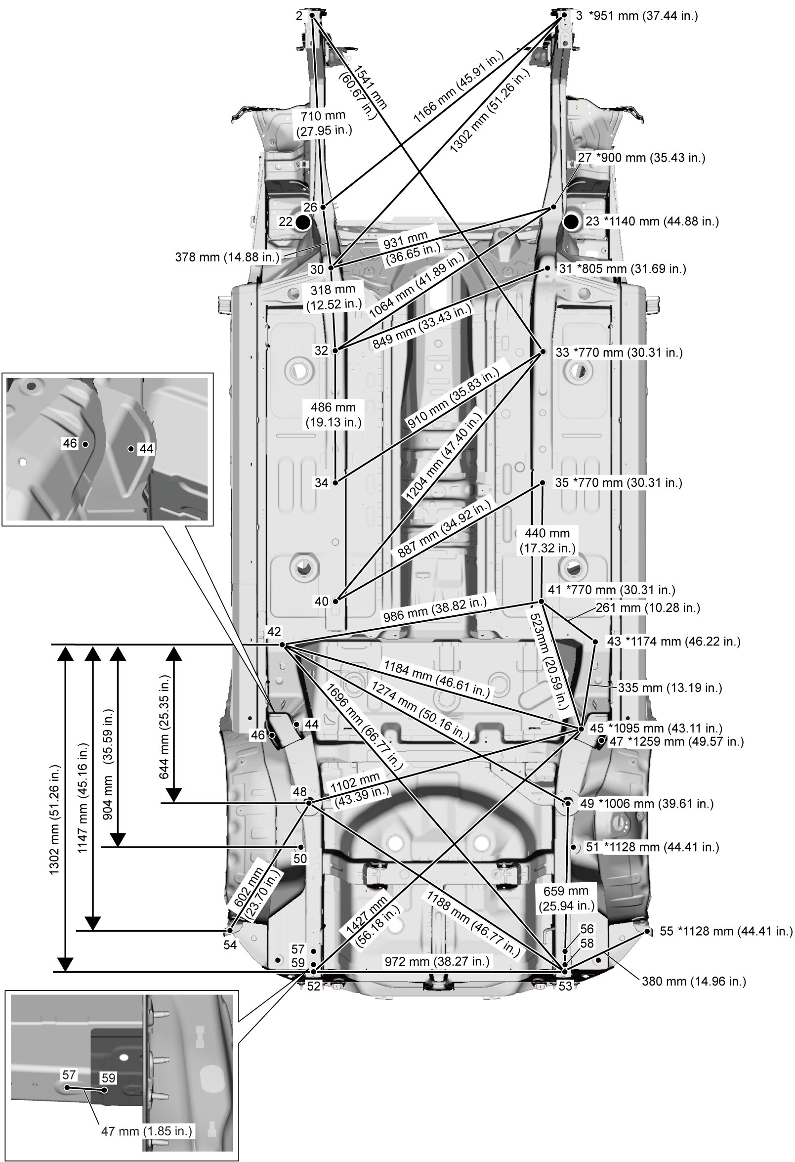
Underbody Dimensions
Precautions: Precautions for Body Structure · Precautions for Body, Cab and Accessories · General safety (00)
NOTE:
•Dimension with asterisk (*) shows distance to the same point on opposite side.
•In principle, body dimensions in the figure below are symmetrical. Adopt the dimension for the opposite side if the dimension is not mentioned in the figure below.
•The number with “ø” is circle diameter and measurement unit is “mm”.
•In principle, body dimensions in the figure below are symmetrical. Adopt the dimension for the opposite side if the dimension is not mentioned in the figure below.
•The number with “ø” is circle diameter and measurement unit is “mm”.
Bottom View (Straight-Line Dimensions)
Side View (Projection Dimensions)
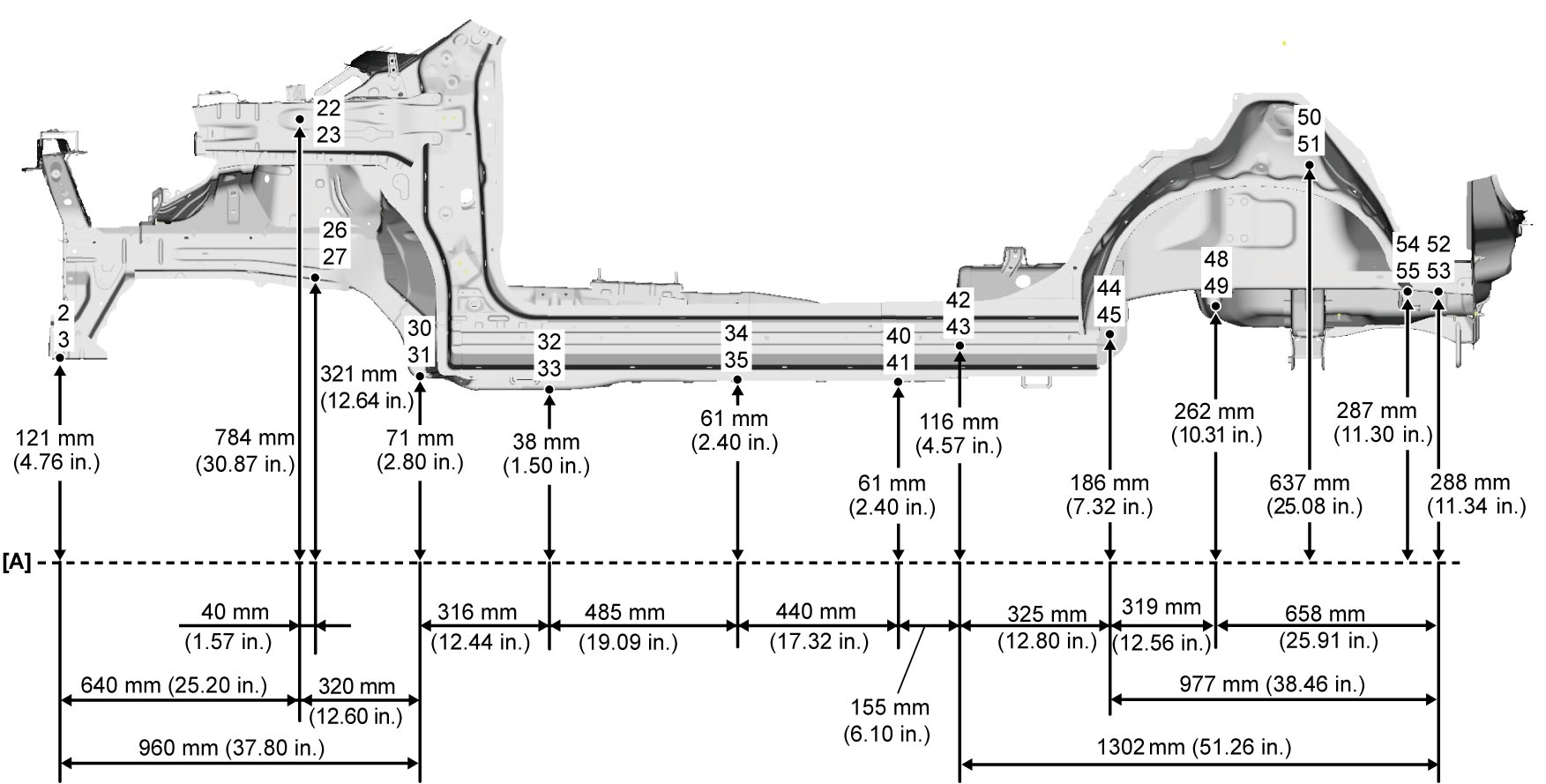
| [A]: | Imaginary datum line |
| Point | Position | ||
|---|---|---|---|
| 2 | Front lower crossmember installation hole | R | ø 11 hole center (weld nut M10) |
| 3 | ↑ | L | ↑ |
| 22 | Front strut installation hole | R | ø 53 hole center |
| 23 | ↑ | L | ↑ |
| 26 | Suspension frame installation hole (front side) | R | ø 18 hole center (weld nut M14) |
| 27 | ↑ | L | ↑ |
| 30 | Suspension frame installation hole (rear side) | R | ø 18 hole center (weld nut M14) |
| 31 | ↑ | L | ↑ |
| 32 | Dash lower member jig hole | R | ø 15 hole center |
| 33 | ↑ | L | ↑ |
| 34 | Floor side rear member jig hole | R | ø 15 hole center |
| 35 | ↑ | L | ↑ |
| 40 | Floor side rear member jig hole | R | ø 15 hole center |
| 41 | ↑ | L | ↑ |
| 42 | Rear floor side front member jig hole | R | ø 25 hole center |
| 43 | ↑ | L | ↑ |
| 44 | Trailing arm installation side (inside hole) | R | ø 13 hole center (weld nut M12) |
| 45 | ↑ | L | ↑ |
| 46 | Trailing arm installation side (outside hole) | R | ø 16.8 hole center |
| 47 | ↑ | L | ↑ |
| 48 | Rear floor side front member jig hole | R | ø 10 hole center |
| 49 | ↑ | L | ↑ |
| 50 | Rear shock absorber installation hole | R | ø 24 hole center |
| 51 | ↑ | L | ↑ |
| 52 | Rear floor side rear member jig hole | R | ø 8 hole center |
| 53 | ↑ | L | ↑ |
| 54 | Rear bumper installation hole | R | ø 8 hole center |
| 55 | ↑ | L | ↑ |
| 56 | Rear floor side rear member jig hole | R | ø 12 hole center |
| 57 | ↑ | L | ↑ |
| 58 | Rear floor side member rear reinforcement jig hole | R | ø 8 hole center |
| 59 | ↑ | L | ↑ |