DTC B1127
Precautions: Precautions for Diagnosing Trouble · Precautions for Control Systems · General safety (00)
DTC Detecting Condition and Trouble Area
| DTC detecting condition | Trouble area |
|---|---|
|
B1127: Driving Mode Switch Circuit Driving mode switch signal circuit voltage is not as specified for specified time continuously. |
•Driving mode switch circuit / connector
•Driving mode switch •BCM |
Circuit Diagram
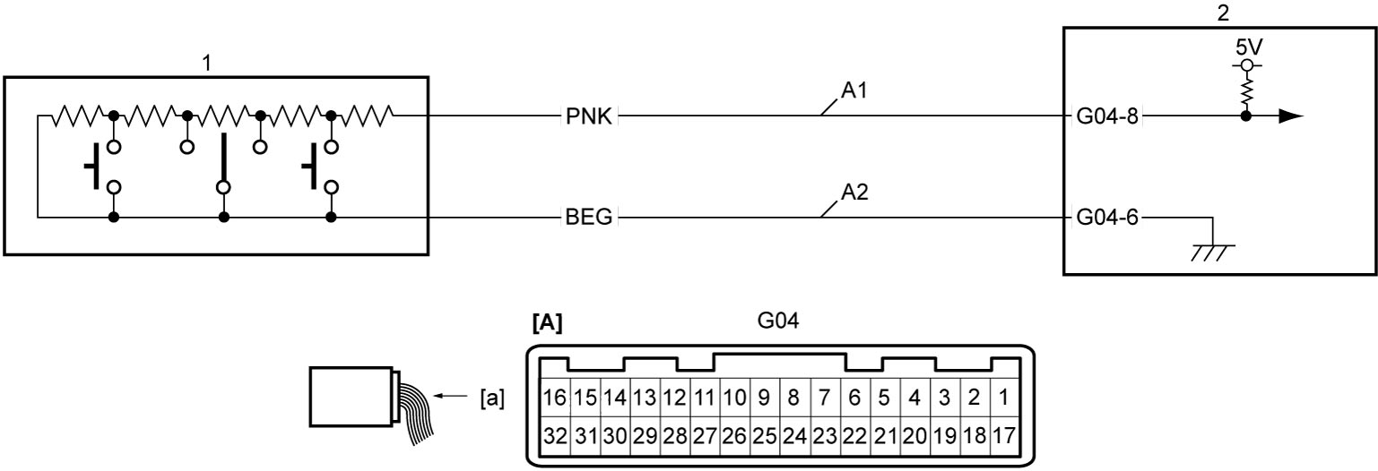
| [A]: | BCM connector (View: [a]) | A2: | Driving mode switch ground circuit | 2. | BCM |
| A1: | Driving mode switch signal circuit | 1. | Driving mode switch |
DTC Confirmation Procedure
1)Set ignition “ON” and leave ignition “ON” for 30 seconds or more.
DTC Troubleshooting
| Step | Action | Yes | No |
|---|---|---|---|
| 1 |
Parameter check
1)Connect SUZUKI scan tool to DLC when ignition is “OFF”.
2)Set ignition “ON”.
3)Check “Driving Mode Switch” displayed on SUZUKI scan tool.

Is check result OK?
|
Check for intermittent trouble.
|
Go to Step 2.
|
| 2 |
Driving mode switch circuit check
1)Check that ignition is “OFF”.
2)Disconnect driving mode switch and “G04” connectors.
3)Check for proper terminal connection to driving mode switch and “G04” connectors.
4)If connections are OK, check the following points.
•Resistance of “A1” and “A2” circuits: less than 1 Ω
•Resistance between “A1” circuit and ground: infinity •Resistance between “A1” and “A2” circuit terminals at driving mode switch connector: infinity •Voltage of “A1” and “A2” circuits: approx. 0 V (When ignition is “ON”) Is check result OK?
|
Go to Step 3.
|
Repair or replace defective wire harness.
|
| 3 |
Driving mode switch check
1)Check driving mode switch.
Is check result OK?
|
Replace BCM and recheck DTC.
|
Replace driving mode switch.
|