DTC B1A00
Precautions: Precautions for Diagnosing Trouble · Precautions for Control Systems · General safety (00)
DTC Detecting Condition and Trouble Area
| DTC detecting condition | Trouble area |
|---|---|
|
B1A00: Battery Voltage Low Power supply circuit voltage is lower than specified value although vehicle has run at 25 km/h (16 mile/h) or more. |
•Power supply circuit / ground circuit
•TPMS control module |
Circuit Diagram
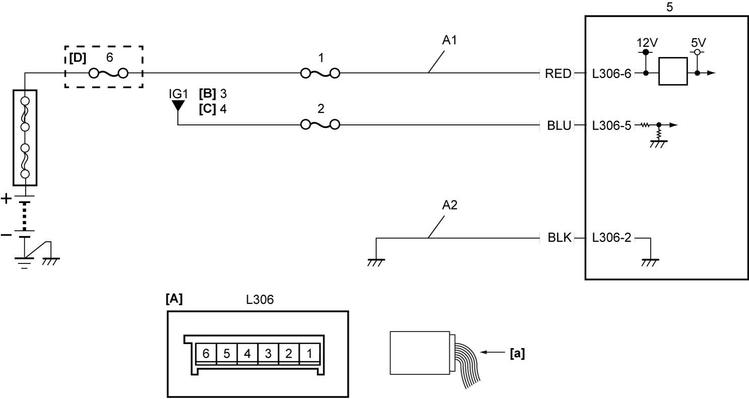
| [A]: | TPMS control module connector (View: [a]) | A1: | TPMS control module power supply circuit | 3. | Ignition switch |
| [B]: | Ignition switch model | A2: | TPMS control module ground circuit | 4. | IG1 relay |
| [C]: | Keyless push start model | 1. | “BCM” fuse | 5. | TPMS control module |
| [D]: | D16AA model | 2. | “CRUISE” fuse | 6. | “BTRY” fuse |
DTC Confirmation Procedure
 WARNING:
If you do not select a suitable route and take proper precautions when performing a road test, an accident can occur.
•Select a level road with no traffic to minimize the risk of accident.
•Perform the test extremely carefully.
•Perform the road test with 2 persons, a driver and a tester.
•Perform the test extremely carefully.
•Perform the road test with 2 persons, a driver and a tester.
1)Drive vehicle at 25 km/h (16 mile/h) or more for 1 minute.
DTC Troubleshooting
| Step | Action | Yes | No |
|---|---|---|---|
| 1 |
TPMS control module power supply circuit check
1)Check that ignition is “OFF”.
2)Disconnect “L306” connector.
3)Check for proper terminal connection to “L306” connector.
4)If OK, check that voltage between “A1” circuit and ground is battery voltage.
Is check result OK?
|
Go to Step 2.
|
Repair or replace defective wire harness.
|
| 2 |
TPMS control module ground circuit check
1)Check that resistance between “A2” circuit and ground is less than 1 Ω.
Is check result OK?
|
Replace TPMS control module and recheck DTC.

|
Repair or replace defective wire harness.
|