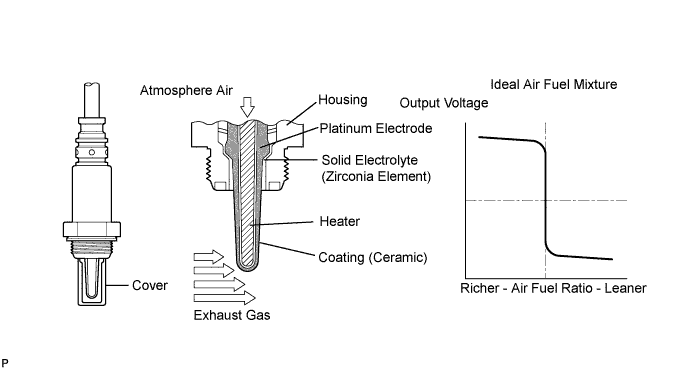
DTC P0136 Oxygen Sensor Circuit Malfunction (Bank 1 Sensor 2) |
DTC P0137 Oxygen Sensor Circuit Low Voltage (Bank 1 Sensor 2) |
DTC P0138 Oxygen Sensor Circuit High Voltage (Bank 1 Sensor 2) |
DTC P0156 Oxygen Sensor Circuit Malfunction (Bank 2 Sensor 2) |
DTC P0157 Oxygen Sensor Circuit Low Voltage (Bank 2 Sensor 2) |
DTC P0158 Oxygen Sensor Circuit High Voltage (Bank 2 Sensor 2) |
| DTC No. | DTC Detection Condition | Trouble Area |
| P0136 P0156 | During active air fuel ratio control, following conditions (a) and (b) are met for certain period of time (2 trip detection logic): (a) Heated Oxygen (HO2) sensor voltage does not decrease to less than 0.2 V (b) HO2 sensor voltage does not increase to more than 0.6 V |
|
| P0136 P0156 | Sensor impedance less than 5 Ω for more than 30 seconds when ECM presumes sensor to being warmed up and operating normally (1 trip detection logic) | |
| P0137 P0157 | During active air fuel ratio control, following conditions (a) and (b) are met for certain period of time (2 trip detection logic): (a) HO2 sensor voltage output less than 0.21 V (b) Target air fuel ratio rich |
|
| P0137 P0157 | High impedance: Sensor impedance 348.1 MΩ or more for more than 90 seconds when ECM presumes sensor to being warmed up and operating normally (1 trip detection logic) | |
| P0138 P0158 | During active air fuel ratio control, following conditions (a) and (b) are met for certain period of time (2 trip detection logic): (a) HO2 sensor voltage output 0.59 V or more (b) Target air fuel ratio lean |
|
| P0138 P0158 | HO2 sensor voltage output exceeds 1.2 V for more than 30 seconds (1 trip detection logic) |
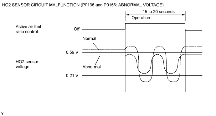
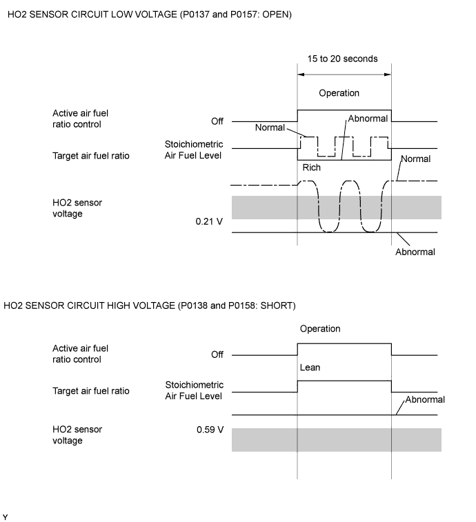
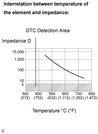 |
| Related DTCs | P0136: Heated oxygen sensor (Bank 1) output voltage (Output voltage) P0136: Heated oxygen sensor (Bank 1) impedance (Low) P0137: Heated oxygen sensor (Bank 1) output voltage (Low voltage) P0137: Heated oxygen sensor (Bank 1) impedance (High) P0138: Heated oxygen sensor (Bank 1) output voltage (High voltage) P0138: Heated oxygen sensor (Bank 1) output voltage (Extremely high) P0156: Heated oxygen sensor (Bank 2) output voltage (Output voltage) P0156: Heated oxygen sensor (Bank 2) impedance (Low) P0157: Heated oxygen sensor (Bank 2) output voltage (Low voltage) P0157: Heated oxygen sensor (Bank 2) impedance (High) P0158: Heated oxygen sensor (Bank 2) output voltage (High voltage) P0158: Heated oxygen sensor (Bank 2) output voltage (Extremely high) |
| Required Sensors/Components (Main) | Heated oxygen sensor |
| Required Sensors/Components (Related) | Mass air flow meter |
| Frequency of Operation | Once per driving cycle: Active air-fuel ratio control detection Continuous: Others |
| Duration | 20 seconds: Heated oxygen sensor output (Output voltage, High voltage, Low voltage) 30 seconds: Heated oxygen sensor impedance (Low) 90 seconds: Heated oxygen sensor impedance (High) 10 seconds: Heated oxygen sensor impedance (Extremely high) |
| MIL Operation | 2 driving cycles |
| Sequence of Operation | None |
| The monitor will run whenever these DTCs are not present | P0031, P0032, P0051, P0052 (A/F sensor heater - Sensor 1) P0037, P0038, P0057, P0058 (O2 sensor heater - Sensor 2) P0100 - P0103 (MAF meter) P0110 - P0113 (IAT sensor) P0115 - P0118 (ECT sensor) P0120 - P0223, P2135 (TP sensor) P0125 (Insufficient ECT for closed loop) P0171, P0172 (Fuel system) P0300 - P0308 (Misfire) P0335 (CKP sensor) P0455, P0456 (EVAP system) P0500 (VSS) P2196, P2198 (A/F sensor - rationality) P2440 (AIR control valve stuck open) P2441 (AIR control valve stuck close) P2444 (AIP stuck ON) P2445 (AIP stuck OFF) P2A00, P2A03 (A/F sensor - slow response) |
| Active air-fuel ratio control | Executing |
| Active air-fuel ratio control being when all of following conditions are met: | - |
| Battery voltage | 11 V or more |
| Engine coolant temperature | 75°C (167°F) or more |
| Idle | OFF |
| Engine RPM | Less than 3,200 rpm |
| A/F sensor status | Activated |
| Fuel-cut | OFF |
| Engine load | 10 to 70 % |
| Shift position | 4th or more |
| Battery voltage | 11 V or higher |
| Estimated sensor temperature | Lower than 700°C (1,292°F) |
| ECM monitor | Completed |
| P0606 | Not set |
| Battery voltage | 11 V or more |
| Estimated sensor temperature | 450°C (842°F) or more |
| P0606 | Not set |
| Battery voltage | 11 V or more |
| Time after engine start | 2 seconds or more |
| Either of the following conditions is met: | Condition 1 or 2 |
| 1. All of the following conditions are met: | Conditions (a), (b) and (c) |
| (a) Commanded air-fuel ratio | 14.3 or less |
| (b) Rear HO2S voltage | 0.21 to 0.59 V |
| (c) OSC (Oxygen Storage Capacity of catalyst) | 3 g or more |
| 2. All of the following conditions are met: | Conditions (a), (b) and (c) |
| (a) Commanded air-fuel ratio | 14.9 or more |
| (b) Rear HO2S voltage | 0.21 to 0.59 V |
| (c) OSC (Oxygen Storage Capacity of catalyst) | 3 g or more |
| All of the following conditions are met: | Conditions 1, 2 and 3 |
| 1. Commanded air-fuel ratio | 14.3 or less |
| 2. Rear HO2S voltage | Less than 0.21 V |
| 3. OSC (Oxygen Storage Capacity of catalyst) | 3 g or more |
| All of the following conditions are met: | Conditions 1, 2 and 3 |
| 1. Commanded air-fuel ratio | 14.9 or more |
| 2. Rear HO2S voltage | More than 0.59 V |
| 3. OSC (Oxygen Storage Capacity of catalyst) | 3 g or more |
| Duration of the following condition | 30 seconds or more |
| Heated oxygen sensor impedance | Less than 5 Ω |
| Duration of the following condition | 90 seconds or more |
| Heated oxygen sensor impedance | 15 KΩ or more |
| Duration of the following condition | 10 seconds or more |
| Heated oxygen sensor impedance | More than 1.2 V |
| Heated Oxygen sensor voltage | Varies between 0.1 and 0.9 V |
| MID | TID | Scaling | Description of Test Value | Minimum Test Limit | Maximum Test Limit |
| $02 | $07 | Multiply by 0.001 (V) | Minimum sensor voltage | Minimum test limit | Maximum test limit |
| $02 | $08 | Multiply by 0.001 (V) | Maximum sensor voltage | Minimum test limit | Maximum test limit |
| $02 | $8F | Multiply by 0.001 (g) | Maximum oxygen storage capacity | 0 | Maximum test limit |
| MID | TID | Scaling | Description of Test Value | Minimum Test Limit | Maximum Test Limit |
| $06 | $07 | Multiply by 0.001 (V) | Minimum sensor voltage | Minimum test limit | Maximum test limit |
| $06 | $08 | Multiply by 0.001 (V) | Maximum sensor voltage | Minimum test limit | Maximum test limit |
| $06 | $8F | Multiply by 0.001 (g) | Maximum oxygen storage capacity | 0 | Maximum test limit |
| Tester Display (Sensor) | Injection Volume | Status | Voltage |
| AFS B1S1 or AFS B2S1 (A/F) | +25 % | Rich | Less than 3.0 |
| AFS B1S1 or AFS B2S1 (A/F) | -12.5 % | Lean | More than 3.35 |
| O2S B1S2 or O2S B2S2 (HO2) | +25 % | Rich | More than 0.5 |
| O2S B1S2 or O2S B2S2 (HO2) | -12.5 % | Lean | Less than 0.4 |
| Case | A/F Sensor (Sensor 1) Output Voltage | HO2 Sensor (Sensor 2) Output Voltage | Main Suspected Trouble Area | ||
| 1 | Injection Volume +25 % -12.5 % |  | Injection Volume +25 % -12.5 % | | - |
| Output Voltage More than 3.35 V Less than 3.0 V |  | Output Voltage More than 0.55 V Less than 0.4 V |  | ||
| 2 | Injection Volume +25 % -12.5 % | | Injection Volume +25 % -12.5 % | |
|
| Output Voltage Almost no reaction |  | Output Voltage More than 0.5 V Less than 0.4 V | | ||
| 3 | Injection Volume +25 % -12.5 % | | Injection Volume +25 % -12.5 % | |
|
| Output Voltage More than 3.35 V Less than 3.0 V | | Output Voltage Almost no reaction | | ||
| 4 | Injection volume +25 % -12.5 % | | Injection Volume +25 % -12.5 % | |
|
| Output Voltage Almost no reaction | | Output Voltage Almost no reaction | | ||
| 1.CHECK OTHER DTC OUTPUT |
Connect the intelligent tester to the DLC3 with CAN VIM.
Turn the ignition switch ON and turn the tester ON.
Enter the following menus: DIAGNOSIS / ENHANCED OBD II / DTC INFO / CURRENT CODES.
Read DTCs.
| Display (DTC Output) | Proceed to |
| P0138 or P0158 | A |
| P0137 or P0157 | B |
| P0136 or P0156 | C |
|
| ||||
|
| ||||
| A | |
 |
| 2.READ VALUE OF INTELLIGENT TESTER (OUTPUT VOLTAGE OF HEATED OXYGEN SENSOR) |
Connect the intelligent tester to the DLC3 with CAN VIM.
After warming up the engine, run the engine at 2,500 rpm for 3 minutes.
Enter the following menus: DIAGNOSIS / ENHANCED OBD II / DATA LIST / ALL / O2S B1S2 or O2S B2S2.
Allow the engine to idle.
Read the Heated Oxygen (HO2) sensor output voltage while idling.
| HO2 Sensor Output Voltage | Proceed to |
| More than 1.2 V | A |
| Less than 1.0 V | B |
|
| ||||
| A | |
|
| 3.CHECK HARNESS AND CONNECTOR (CHECK FOR SHORT) |
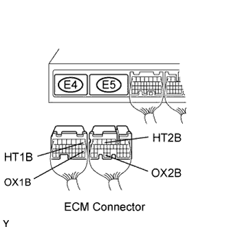 |
Turn the ignition switch OFF and wait for 5 minutes.
Disconnect the E4 and E5 ECM connectors.
Check the resistance.
| Tester Connection | Specified Condition |
| HT1B (E4-1) - OX1B (E4-18) | 10 kΩ or higher |
| HT2B (E5-5) - OX2B (E5-33) | 10 kΩ or higher |
Reconnect the ECM connector.
|
| ||||
| OK | ||
 | ||
| ||
| 4.INSPECT HEATED OXYGEN SENSOR (CHECK FOR SHORT) |
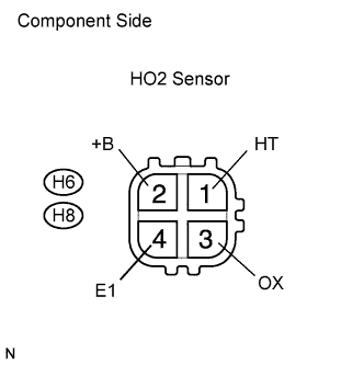 |
Disconnect the H6 or H8 Heated Oxygen (HO2) sensor connector.
Measure the resistance of the HO2 sensor connector.
| Tester Connection | Specified Condition |
| HT (1) - +B (2) | 11 to 16 Ω at 20°C (68°F) |
| HT (1) - E1 (4) | 10 kΩ or higher |
Reconnect the HO2 sensor connector.
|
| ||||
| OK | ||
| ||
| ||
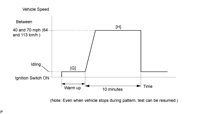
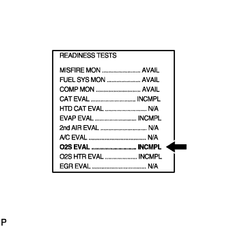
| 5.PERFORM CONFIRMATION DRIVING PATTERN |
| NEXT | |
|
| 6.READ OUTPUT DTC (DTC P0138, P0158) |
Enter the following menu items: DIAGNOSIS / ENHANCED OBD II / DTC INFO / PENDING CODES.
Read DTCs.
| Display (DTC Output) | Proceed to |
| No output | A |
| P0136 and/or P0156 | B |
|
| ||||
| B | ||
| ||
| ||
| 7.READ VALUE OF INTELLIGENT TESTER (OUTPUT VOLTAGE OF HEATED OXYGEN SENSOR) |
Connect the intelligent tester to the DLC3 with CAN VIM.
Turn the ignition switch ON and turn the tester ON.
Start the engine.
Enter the following menus: DIAGNOSIS / ENHANCED OBD II / DATA LIST / ALL / O2S B1S2.
After warming up the engine, run the engine at an engine speed of 2,500 rpm for 3 minutes.
Read the output voltage of the HO2 sensor when the engine rpm is suddenly increased.
|
| ||||
| OK | |
|
| 8.PERFORM CONFIRMATION DRIVING PATTERN |
| NEXT | |
|
| 9.READ DTC OUTPUT (DTC P0138, P0158) |
On the intelligent tester, enter the following menus: DIAGNOSIS / ENHANCED OBD II / DTC INFO / PENDING CODES.
Read DTCS.
| Display (DTC Output) | Proceed to |
| P0136 or P0156 | A |
| No output | B |
|
| ||||
| A | |
|
| 10.REPLACE HEATED OXYGEN SENSOR |
Replace HO2 sensor .
| NEXT | |
|
| 11.PERFORM CONFIRMATION DRIVING PATTERN |
| NEXT | |
|
| 12.READ DTC OUTPUT (DTC P0138 or P0158) |
On the intelligent tester, enter the following menus: DIAGNOSIS / ENHANCED OBD II / DTC INFO / PENDING CODES.
Read DTCs.
| Display (DTC Output) | Proceed to |
| P0136 or P0156 | A |
| No output | B |
|
| ||||
| A | |
|
| 13.PERFORM ACTIVE TEST BY INTELLIGENT TESTER (INJECTION VOLUME) |
Connect the intelligent tester to the DLC3 with CAN VIM.
Start the engine and turn the tester ON.
Warn up the engine.
Enter the following menus: DIAGNOSIS / ENHANCED OBD II / ACTIVE TEST / INJ VOL.
Change the injection volume using the tester, monitoring the voltage output of Air Fuel Ratio (A/F) and HO2 sensors displayed on the tester.
| Tester Display (Sensor) | Voltage Variations | Proceed to |
| AFS B1S1 (AFS B2S1) (A/F) | Alternates between more than 3.3 V and less than 3.3 V | OK |
| AFS B1S1 (AFS B2S1) (A/F) | Remains at more than 3.3 V | NG |
| AFS B1S1 (AFS B2S1) (A/F) | Remains at less than 3.3 V | NG |
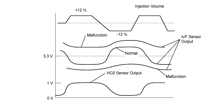
|
| ||||
| OK | ||
| ||
| ||
| 14.CHECK FOR EXHAUST GAS LEAKAGE |
Check for exhaust gas leakage from the exhaust manifold and pipe.
|
| ||||
| OK | |
|
| 15.INSPECT HEATED OXYGEN SENSOR (HEATER RESISTANCE) |
|
Disconnect the H6 or H8 HO2 sensor connector.
Measure the resistance of the HO2 sensor connector.
| Tester Connection | Specified Condition |
| HT (1) - +B (2) | 11 to 16 Ω at 20°C (68°F) |
| HT (1) - E1 (4) | 10 kΩ or higher |
Reconnect the HO2 sensor connector.
|
| ||||
| OK | |
|
| 16.INSPECT EFI RELAY |
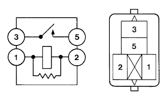 |
Remove the EFI relay from the engine room relay block.
Measure the resistance of the EFI relay.
| Tester Connection | Specified Condition |
| 3 - 5 | 10 kΩ or higher |
| 3 - 5 | Below 1 Ω (when battery voltage is applied to terminals 1 and 2) |
Reinstall the EFI relay.
|
| ||||
| OK | |
|
| 17.CHECK HARNESS AND CONNECTOR (ECM - HEATED OXYGEN SENSOR) |
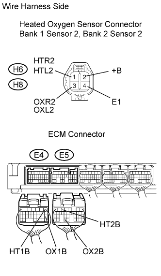 |
Disconnect the heated oxygen sensor connector.
Disconnect the E4 and E5 ECM connector.
Measure the resistance between the wire harness side connectors.
| Tester Connection | Specified Condition |
| OXL2 (H6-3) - OX1B (E4-18) | Below 1 Ω |
| HTL2 (H6-1) - HT1B (E4-1) | Below 1 Ω |
| OXR2 (H8-3) - OX2B (E5-33) | Below 1 Ω |
| HTR2 (H8-1) - HT2B (E5-5) | Below 1 Ω |
| OXL2 (H6-3) or OX1B (E4-18) - Body ground | 10 kΩ or higher |
| HTL2 (H6-1) or HT1B (E4-1) - Body ground | 10 kΩ or higher |
| OXR2 (H8-3) or OX2B (E5-33) Body ground | 10 kΩ or higher |
| HTR2 (H8-1) or HT2B (E5-5) - Body ground | 10 kΩ or higher |
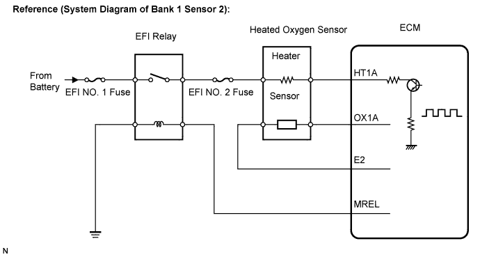
|
| ||||
| OK | ||
| ||
| ||

