| A |  |
| GO TO DTC B1771 |
DTC B1795 Occupant Classification ECU Malfunction |
| DTC No. | DTC Detecting Condition | Trouble Area |
| B1795 |
|
|
| 1.CHECK DTC |
Turn the ignition switch to the ON position, and wait for at least 10 seconds.
Check the DTCs (Click here).
|
| ||||
| B | |
 |
| 2.CHECK FUSE |
Measure the resistance of the ECU-B fuse.
|
| ||||
| OK | |
|
| 3.CHECK WIRE HARNESS (SOURCE VOLTAGE) |
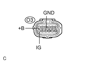 |
Turn the ignition switch to the LOCK position.
Disconnect the negative (-) terminal cable from the battery.
Disconnect the connector from the occupant classification ECU.
Connect the negative (-) terminal cable to the battery.
Turn the ignition switch to the ON position.
Measure the voltage according to the value(s) in the table below.
| Tester connection | Condition | Specified condition |
| O3-1 (+B) - Body ground | Always | 10 to 14 V |
| O3-7 (IG) - Body ground | Ignition switch ON | 10 to 14 V |
Turn the ignition switch to the LOCK position.
Measure the resistance according to the value(s) in the table below.
| Tester connection | Condition | Specified condition |
| O3-3 (GND) - Body ground | Always | Below 1 Ω |
|
| ||||
| OK | |
|
| 4.REPLACE OCCUPANT CLASSIFICATION ECU |
Turn the ignition switch to the LOCK position.
Disconnect the negative (-) terminal cable from the battery.
Replace the occupant classification ECU (Click here).
| NEXT | |
|
| 5.PERFORM ZERO POINT CALIBRATION |
Connect the negative (-) terminal cable to the battery.
Connect the intelligent tester to the DLC3.
Turn the ignition switch to the ON position.
Using the intelligent tester, perform "Zero point calibration" (Click here).
| NEXT | |
|
| 6.PERFORM SENSITIVITY CHECK |
Using the intelligent tester, perform "Sensitivity check" (Click here).
| NEXT | ||
 | ||
| ||