Home › SUSPENSION & AXLE › SUSPENSION CONTROL › AIR SUSPENSION SYSTEM

DTC    C1751/51    Continuous Electric Current to Height Control Compressor

for Preparation Click here


DESCRIPTION


DTC No.
DTC Detecting Condition
Trouble Area
C1751/51*1
With the AIR SUS relay activated, the vehicle does not go up to the standard vehicle height after 90 sec. have elapsed.
  1. Height control compressor assembly
  2. Height control compressor circuit
  3. Height control sensor circuit
  4. Height control sensor link sub-assembly
  5. Relief valve
  6. AIR SUS relay circuit
  7. Air leakage from the air tube or each valve
  8. Clogging in the air tube or each valve
  9. Suspension control ECU
*1: The relief pressure of the compressed air is 980 kPa (10 kgf/cm2, 142 psi).
If the vehicle height control is attempted on a steeply sloping road, when the vehicle is overloaded, or when the vehicle is jacked up with the engine running, the compressor motor operates continuously to raise vehicle height, and causes electric current to flow to the AIR SUS relay for 100 seconds or longer.
Thus DTC C1751/51 may be output and vehicle height control may be suspended. (This is not electrically abnormal.) In this case, however, the vehicle height operation is resumed approx. 10 min. after the ignition switch is turned ON after the ECU detects the first error. If ECU detects another error, it takes 70 minutes until control is resumed.

INSPECTION PROCEDURE

1.INSPECT HEIGHT CONTROL COMPRESSOR CIRCUIT
  1. Inspect the height control compressor circuit (Click here).


NEXT


2.INSPECT AIR LEAKAGE
  1. Check tube connections for air leakage (Click here).

    OK:
    No leaks


NG
REPAIR OR REPLACE AIR TUBE
OK


3.INSPECT HEIGHT CONTROL VALVE (GATE SOLENOID, LEVELING SOLENOID, EXHAUST SOLENOID VALVE)
  1. When using intelligent tester:

    1. Connect the intelligent tester to the DLC3.

    2. Turn the ignition switch ON, and push the intelligent tester main switch ON.

    3. Select the item "LEVEL SOL REAR", "GATE SOL REAR", "LOW PRS TNK SOL", "EXHAUST SOL" in the ACTIVE TEST, and operate it with the intelligent tester.

    4. Check whether the solenoid makes a sound.

    5. Check whether the height control solenoid valve has continuity (will vibrate).
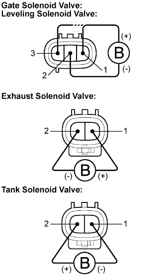
      OK:
      The solenoid makes a sound, and the height control solenoid valve has continuity. (It will vibrate.)


    F044510E01
  1. When not using intelligent tester:

    1. Disconnect the valve connectors.

    2. Check the operating sound of the valves when battery positive voltage is applied to the terminals as shown below.
      Solenoid valve
      Battery positive
      Battery negative
      Gate solenoid valve
      1
      2
      Leveling solenoid valve
      3
      2
      Exhaust solenoid valve
      1
      2
      Tank solenoid valve
      2
      1

      OK:
      It makes an operating sound (click).

      HINT:
      1. When a malfunction is found in the gate solenoid valve, the leveling valve or the tank solenoid valve, replace the height control reservoir assembly.
      2. When a malfunction is found in the exhaust solenoid valve, replace the height control compressor assembly.


B
REPLACE HEIGHT CONTROL RESERVOIR ASSEMBLY

C
REPLACE HEIGHT CONTROL COMPRESSOR ASSEMBLY
A


4.INSPECT HEIGHT CONTROL SENSOR LINK SUB-ASSEMBLY
  1. Inspect and adjust the height control sensor link sub-assembly.


NEXT


5.CONFIRM DTC
  1. Clear the DTC and repeat the procedure to re-check it (Click here).

    HINT:
    If the DTC C1751/51 is still output, proceed to the next step.


NEXT

REPAIR OR REPLACE PARTS AND COMPONENTS INDICATED BY OUTPUT DTCS