Home › ENGINE ยท 2UZ-FE › LUBRICATION › OIL PUMP

OIL PUMP > INSTALLATION

for Preparation Click here


1. INSTALL OIL PUMP ASSEMBLY


    B000960E04
  1. Remove any old packing (FIPG) material and be careful not to drop any oil on the contact surfaces of the oil pump and cylinder block.

    1. Using a gasket scraper, remove all the old packing (FIPG) material from the gasket surfaces and sealing groove.

    2. Thoroughly clean all components to remove all the loose material.

    3. Using a non-residue solvent, clean both sealing surfaces.
  1. Install a new oil pump seal .

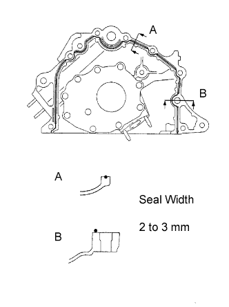
  1. Apply seal packing to the oil pump as shown in the illustration.

    Seal packing:
    Part No. 08826-00080 or equivalent

    NOTICE:
    Avoid applying an excessive amount to the surface. Be particularly careful around the oil passages.


    1. Use a nozzle that has been cut to a 2 to 3 mm (0.08 to 0.12 in.) opening.

    2. Parts must be assembled within 3 minutes of application. Otherwise the material must be removed and reapplied.

    3. Immediately remove the nozzle from the tube and reinstall the cap.


    P021388E02
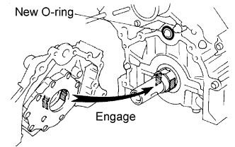
  1. Install a new O-ring to the cylinder block.

  1. Engage the spline teeth of the oil pump drive gear with the large teeth of the crankshaft, and slide the oil pump on the crankshaft.


    B000950E01
  1. Install the new pump with the 8 bolts. Uniformly tighten the bolts in several steps.

    Torque:
    14 mm:
    31 N*m{ 311 kgf*cm , 23 ft.*lbf }
    For others:
    16 N*m{ 160 kgf*cm , 11 ft.*lbf }


2. INSTALL OIL PAN SUB-ASSEMBLY


    A072709E01
  1. Remove any old packing (FIPG) material and be careful not to drop any oil on the contact surfaces of the No. 1 oil pan, cylinder block, oil pump and rear oil seal retainer.

    1. Using a razor blade and gasket scraper, remove all the old packing (FIPG) material from the gasket surfaces and sealing groove.
    2. Thoroughly clean all components to remove all the loose material.
    3. Using a non-residue solvent, clean both sealing surfaces.
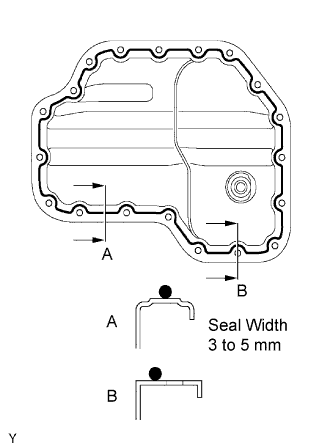
  1. Apply seal packing to the No. 1 oil pan as shown in the illustration.

    Seal packing:
    Part No. 08826-00080 or equivalent

    1. Use a nozzle that has been cut to a 3 to 5 mm (0.12 to 0.20 in.) opening.
    2. Parts must be assembled within 5 minutes of application. Otherwise the material must be removed and reapplied.
    3. Immediately remove the nozzle from the tube and reinstall the cap.


    A072710E01
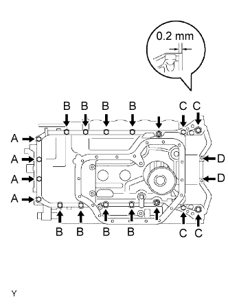
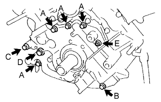
  1. Temporarily install the oil pan with the 18 bolts and 2 nuts.

    HINT:
    The following chart is the reference for the oil pump bolt length.

    Bolt
    Size of Bolt Head
    Length
    A
    10 mm
    20 mm (0.79 in.)
    B
    12 mm
    25 mm (0.98 in.)
    C
    12 mm
    60 mm (2.36 in.)
    D
    10 mm
    35 mm (1.38 in.)

  1. Set the oil pan as shown in the illustration.

    NOTICE:
    Make sure that the clearance between the rear end of the oil pan and cylinder block is 0.2 mm (0.008 in.) or less.
    If the clearance is more than 0.2 mm (0.008 in.), the oil pan will be stretched.

  1. Uniformly tighten the bolts and nuts diagonally.

    Torque:
    For bolts A and D:
    7.5 N*m{ 76 kgf*cm , 66 in.*lbf }
    For bolts B, C and nut:
    28 N*m{ 286 kgf*cm , 21 ft.*lbf }


3. INSTALL OIL PAN BAFFLE PLATE


    A072705
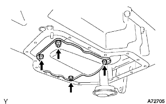
  1. Install the baffle plate with the 2 bolts and 2 nuts.

    Torque:
    7.5 N*m{ 76 kgf*cm , 66 in.*lbf }

    HINT:
    Use bolts 12 mm (0.47 in.) in length.


4. INSTALL OIL STRAINER SUB-ASSEMBLY


    A072708
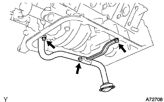
  1. Install a new gasket and the oil strainer with the 2 bolts and 2 nuts.

    Torque:
    7.5 N*m{ 76 kgf*cm , 66 in.*lbf }

    HINT:
    Use bolts 12 mm (0.47 in.) in length.


5. INSTALL NO. 2 OIL PAN SUB-ASSEMBLY


    A072711E01
  1. Remove any oil packing (FIPG) material and be careful not to drop any oil on the contact surfaces of the No. 1 and No. 2 oil pans.

    1. Using a razor blade and gasket scraper, remove all the old packing (FIPG) material from the gasket surfaces and sealing groove.
    2. Thoroughly clean all components to remove all the loose material.
    3. Using a non-residue solvent, clean both sealing surfaces.
    NOTICE:
    Do not use a solvent which will affect the painted surfaces.

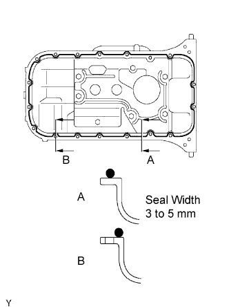
  1. Apply seal packing to the No. 2 oil pan as shown in the illustration.

    Seal packing:
    Part No. 08826-00080 or equivalent

    1. Use a nozzle that has been cut to a 3 to 5 mm (0.12 to 0.20 in.) opening.
    2. Parts must be assembled within 5 minutes of application. Otherwise the material must be removed and reapplied.
    3. Immediately remove the nozzle from the tube and reinstall the cap.

  1. Install the No. 2 oil pan with the 17 bolts and 2 nuts. Uniformly tighten the bolts and nuts in several steps.

    Torque:
    7.5 N*m{ 76 kgf*cm , 66 in.*lbf }

    HINT:
    Use bolts 14 mm (0.55 in.) in length.


6. INSTALL OIL COOLER ASSEMBLY
  1. Clean the oil cooler contact surface on the cooler mounting.

  1. Install a new O-ring to the oil cooler.

  1. Apply a light coat of engine oil on the threads and under the head of the union bolt.

  1. Install the plate washer and union bolt.

    Torque:
    69 N*m{ 700 kgf*cm , 51 ft.*lbf }

  1. Connect the 2 oil cooler hoses to the cooler.


7. INSTALL CRANKSHAFT POSITION SENSOR


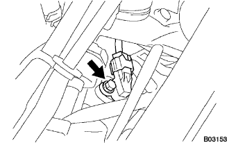
    B003153
  1. Install crank position sensor with bolt.

    Torque:
    6.5 N*m{ 65 kgf*cm , 58 in.*lbf }

  1. Reconnect the crank position sensor connector.


8. INSTALL CRANKSHAFT TIMING PULLEY


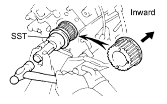
    A004446E01
  1. Fit the timing pulley set key to the key groove of the pulley.

  1. Using SST and a hammer, tap in the timing pulley with the flange side facing inward.

    SST
    09223-46011  


9. INSTALL TIMING BELT
  1. Install timing belt (Click here).


10. INSTALL ENGINE ASSEMBLY
  1. Install engine assembly (Click here).