 |
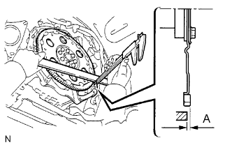
Using calipers and a straight edge, measure dimension A between the transmission and the end surface of the drive plate.
AUTOMATIC TRANSMISSION ASSEMBLY (for 1GR-FE) > INSTALLATION |
| 1. INSTALL TORQUE CONVERTER CLUTCH ASSEMBLY |
|
Using calipers and a straight edge, measure dimension A between the transmission and the end surface of the drive plate.
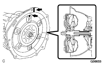 |
Aligning the matchmarks on the transmission case and torque converter assembly, engage the splines of the input shaft and turbine runner.
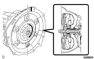 |
Engage the splines of the stator shaft and stator while turning the torque converter assembly.
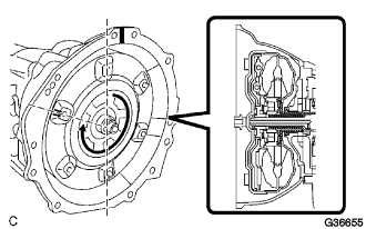 |
Turn the torque converter assembly and align the matchmarks on the torque converter assembly and transmission case to engage the key of the oil pump drive gear into the slot on the torque converter assembly. (procedure "1")
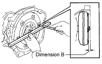 |
Using calipers and a straight edge, measure dimension B shown in the illustration and check that B is greater than A measured in procedure "1".
| 2. INSTALL TRANSFER ASSEMBLY |
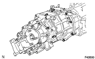 |
Remove the 8 bolts and 2 clamps.
Remove the transfer from the automatic transmission.
| 3. INSTALL NO.1 TRANSMISSION CONTROL CABLE BRACKET |
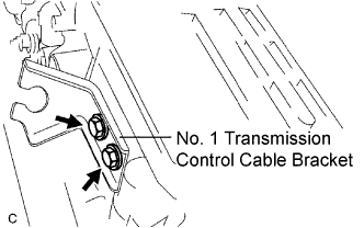 |
Install the No. 1 transmission control cable bracket to the transmission assembly with the 2 bolts.
| 4. INSTALL TRANSFER BREATHER HOSE SUB-ASSEMBLY |
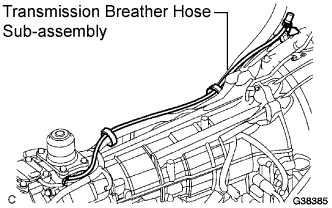 |
Install the transfer breather hose sub-assembly.
| 5. INSTALL AUTOMATIC TRANSMISSION ASSEMBLY |
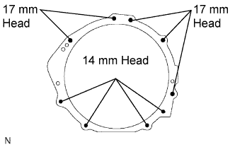 |
Install the automatic transmission assembly to the engine with the 9 bolts.
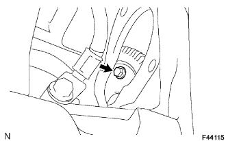 |
Install the 6 torque converter mounting bolts.
Install the torque converter housing side cover to the engine.
| 6. INSTALL NO.1 REAR ENGINE MOUNTING INSULATOR |
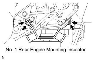 |
Install the No. 1 rear engine mounting insulator to the automatic transmission with the 4 bolts.
| 7. INSTALL FRONT DIFFERENTIAL ASSEMBLY |
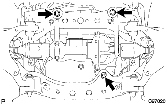 |
Connect the actuator hose and connector.
Install the No. 1 mounting support with the 3 bolts.
Install the No. 2 mounting support with the 2 bolts.
Install the No. 3 front differential support with the 2 bolts.
Support the front differential with a jack.
Install the 2 front mounting bolts and nuts.
Install the No. 1 front differential mount nut.
Install the front differential breather tube bracket with the bolt.
Lower the jack.
| 8. INSTALL NO.2 MANIFOLD STAY |
| 9. INSTALL MANIFOLD STAY |
| 10. INSTALL STARTER ASSEMBLY |
| 11. CONNECT CONNECTOR |
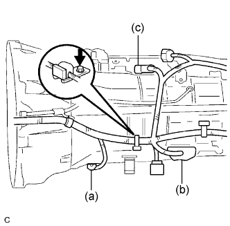
Transmission side:
 |
Connect the speed sensor SP2 connector(a).
Install the wire harness with the bolt.
Connect the speed sensor NT connector (b).
Connect the transmission wire connector (c).
 |
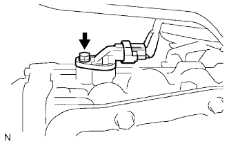
Connect the park/neutral position switch assembly connector .
Transfer side:
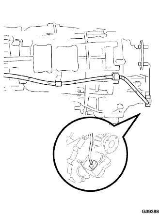 |
Connect the transfer shift actuator connector. (with transfer shift actuator)
| 12. INSTALL NO.3 FRAME CROSSMEMBER SUB-ASSEMBLY |
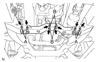 |
Install the No. 3 frame crossmember sub-assembly with the 4 bolts and 4 nuts.
Tighten the 4 bolts to the No. 3 frame crossmember sub-assembly and No. 1 engine mounting insulator rear.
| 13. CONNECT TRANSMISSION CONTROL CABLE ASSEMBLY |
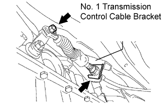 |
Connect the transmission control cable assembly to the automatic transmission.
Install the nut and clip on the transmission control cable assembly.
| 14. INSTALL NO.1 OIL COOLER OUTLET TUBE |
Temporarily install the No. 1 oil cooler outlet tube.
Temporarily install the No. 1 oil cooler inlet tube.
Install the 2 clamps and 2 bolts.
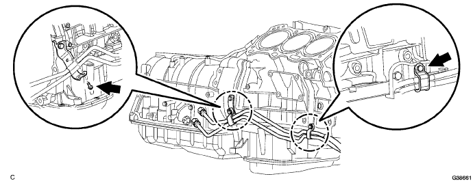
Using SST, tighten the No. 1 oil cooler outlet tube.
| 15. INSTALL NO.1 OIL COOLER INLET TUBE |
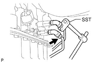 |
Using SST, tighten the No. 1 oil cooler inlet tube.
| 16. INSTALL FRONT SUSPENSION MEMBER BRACKET LH |
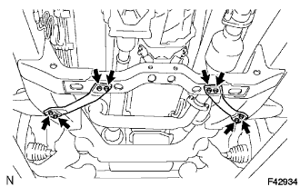 |
Install the front suspension member bracket LH with the 4 bolts.
| 17. INSTALL FRONT SUSPENSION MEMBER BRACKET |
Install the front suspension member bracket with the 4 bolts.
| 18. INSTALL PROPELLER SHAFT HEAT INSULATOR |
Install the propeller shaft heat insulator with the 2 bolts.
| 19. INSTALL PROPELLER SHAFT ASSEMBLY |
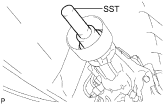 |
Remove the SST from the extension housing.
Install the propeller shaft assembly in the extension housing.
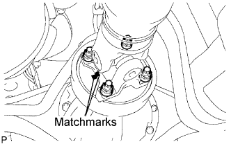 |
Align the matchmarks on the propeller shaft flange and differential flange.
Install the propeller shaft assembly with the 4 nuts and 4 washers.
| 20. INSTALL FRONT PROPELLER SHAFT ASSEMBLY |
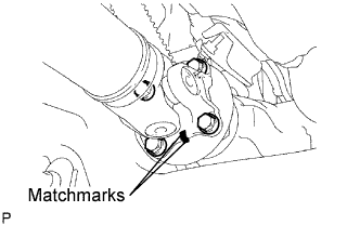 |
Align the matchmarks on the yoke and differential flange.
Install the propeller shaft assembly with the 4 bolts, 4 nuts and 4 washers.
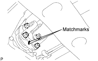 |
Align the matchmarks on the yoke and transfer flange.
Install the propeller shaft assembly with the 4 nuts and 4 washers.
| 21. INSTALL EXHAUST PIPE |
| 22. INSTALL OXYGEN SENSOR |
| 23. INSTALL NO.1 ENGINE UNDER COVER SUB-ASSEMBLY |
| 24. INSTALL REAR ENGINE UNDER COVER ASSEMBLY |
| 25. ADD AUTOMATIC TRANSMISSION FLUID |
| 26. INSPECT AUTOMATIC TRANSMISSION FLUID |
| 27. ADJUST SHIFT LEVER POSITION |
| 28. INSPECT SHIFT LEVER POSITION |
| 29. CHECK FOR EXHAUST GAS LEAKS |
| 30. RESET MEMORY |