 |
Remove the service hole cover from the engine under cover.
CYLINDER HEAD > REMOVAL |
| 1. DISCHARGE FUEL SYSTEM PRESSURE |
| 2. DRAIN ENGINE COOLANT |
|
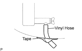
Remove the service hole cover from the engine under cover.
Install a vinyl hose onto the drain on the radiator side.
Fix the vinyl hose with tape.
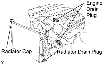 |
Loosen the 3 drain plugs on the engine and radiator, and drain the coolant.
Remove the radiator cap.
Drain the coolant from the reservoir tank.
Tighten the 3 drain plugs.
Remove the vinyl hose from the radiator.
| 3. DRAIN ENGINE OIL |
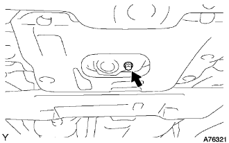 |
Remove the engine under cover seal No. 3.
Remove the oil pan drain plug and drain the engine oil.
Clean the oil pan drain plug and install it with a new gasket.
| 4. REMOVE CHAIN SUB-ASSEMBLY |
| 5. REMOVE NO. 1 COOL AIR INLET |
Remove the 2 bolts and cool air inlet with air cleaner hose.
| 6. REMOVE TRANSMISSION OIL FILLER TUBE SUB-ASSEMBLY |
Remove the ATF level gauge.
Remove the bolt and pull out the oil filler tube.
Remove the O-ring from the oil filler tube.
| 7. REMOVE EXHAUST PIPE ASSEMBLY FRONT |
| 8. REMOVE MANIFOLD STAY |
Remove the 3 bolts and manifold stay.
| 9. REMOVE EXHAUST MANIFOLD SUB-ASSEMBLY RH |
Disconnect the A/F sensor connector.
Remove the 6 nuts, exhaust manifold and gasket.
| 10. REMOVE NO. 2 EXHAUST FRONT PIPE ASSEMBLY |
Remove the 2 bolts, 2 nuts and No. 2 exhaust front pipe assembly.
| 11. REMOVE NO. 2 MANIFOLD STAY |
Remove the 3 bolts and No. 2 manifold stay.
| 12. REMOVE EXHAUST MANIFOLD SUB-ASSEMBLY LH |
Disconnect the A/F sensor connector.
Remove the 6 nuts, exhaust manifold and gasket.
| 13. DISCONNECT NO. 1 FUEL PIPE SUB-ASSEMBLY |
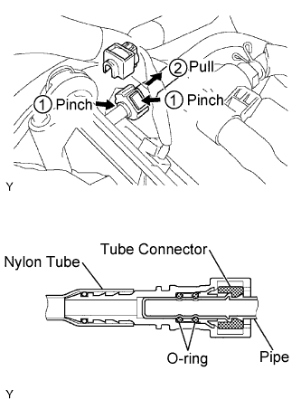 |
Remove the fuel pipe clamp.
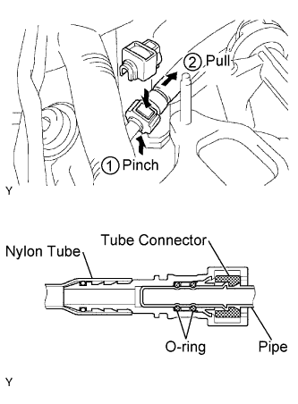
Pinch the tube connector, and then pull the fuel pipe out of the pipe as shown in the illustration.
| 14. DISCONNECT NO. 2 FUEL PIPE SUB-ASSEMBLY |
 |
Remove the fuel pipe clamp.
Pinch the tube connector, and then pull the fuel pipe out of the pipe as shown in the illustration.
| 15. REMOVE INTAKE MANIFOLD |
Disconnect the 6 fuel injector connectors.
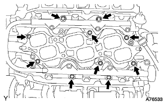 |
Remove the 10 bolts, intake manifold and 2 gaskets.
| 16. REMOVE WATER BY-PASS JOINT RR |
Disconnect the engine coolant temperature sensor connector.
Disconnect the heater hose.
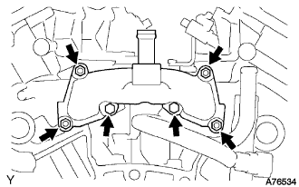 |
Remove the 2 bolts, 4 nuts, water by-pass joint RR and 2 gaskets.
Remove the O-ring from the water outlet pipe.
| 17. REMOVE CAMSHAFT TIMING GEARS AND NO. 2 CHAIN (for Bank 1) |
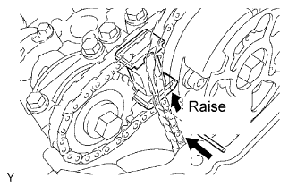 |
While raising the No. 2 chain tensioner, insert a pin of φ1.0 mm (0.039 in.) into the hole to fix it.
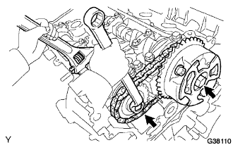 |
Hold the hexagonal portion of the camshaft with a wrench, and remove the 2 bolts, camshaft timing gear, camshaft timing gear assembly and No. 2 timing chain.
| 18. REMOVE NO. 2 CHAIN TENSIONER ASSEMBLY |
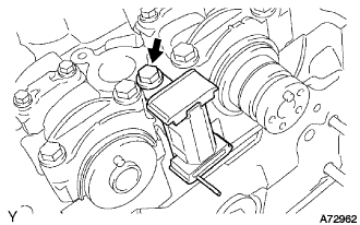 |
Remove the bolt and No. 2 chain tensioner.
| 19. REMOVE CAMSHAFTS (for Bank 1) |
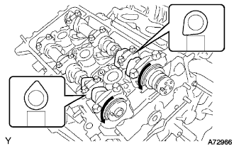 |
Rotate the camshafts counterclockwise using a wrench so that the cam lobes of No. 1 cylinder face each direction as shown in the illustration.
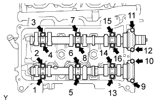 |
Using several steps, loosen and remove the 16 bearing cap bolts uniformly in the sequence as shown in the illustration.
Remove the 8 bearing caps and 2 camshafts.
| 20. REMOVE NO. 2 CAMSHAFT BEARING |
| 21. REMOVE NO. 1 CHAIN VIBRATION DAMPER |
Remove the 2 bolts and No. 1 chain vibration damper.
| 22. REMOVE CAMSHAFT TIMING GEARS AND NO. 2 CHAIN (for Bank 2) |
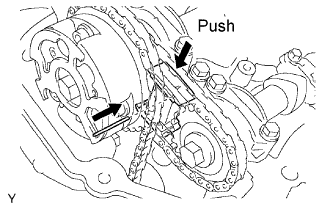 |
While pushing down the No. 3 chain tensioner, insert a pin of φ1.0 mm (0.039 in.) into the hole to fix it.
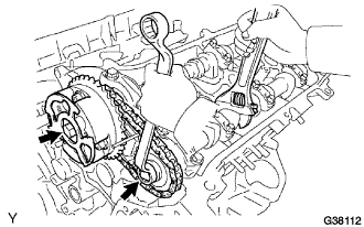 |
Hold the hexagonal portion of the camshaft with a wrench, and remove the 2 bolts, camshaft timing gear, camshaft timing gear assembly and No. 2 timing chain.
| 23. REMOVE NO. 3 CHAIN TENSIONER ASSEMBLY |
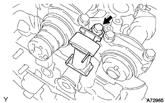 |
Remove the bolt and No. 3 chain tensioner.
| 24. REMOVE CAMSHAFTS (for Bank 2) |
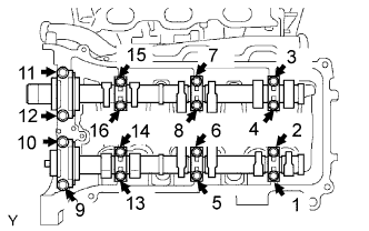 |
Using several steps, loosen and remove the 16 bearing cap bolts uniformly in the sequence as shown in the illustration.
Remove the 8 bearing caps and 2 camshafts.
| 25. REMOVE CYLINDER HEAD SUB-ASSEMBLY |
Remove the 2 bolts and separate the 2 ground cables.
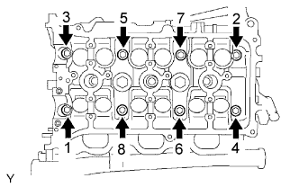 |
Using several steps, loosen the 8 cylinder head bolts on the cylinder head uniformly with a 10 mm bi-hexagon wrench in the sequence as shown in the illustration. Remove the 8 cylinder head bolts and plate washers.
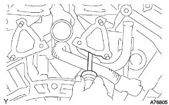 |
Lift the cylinder head from the dowels on the cylinder block, and place the cylinder head on wooden blocks on a bench.
| 26. REMOVE CYLINDER HEAD GASKET |
| 27. REMOVE CYLINDER HEAD LH |
Remove the bolt and separate the ground cable.
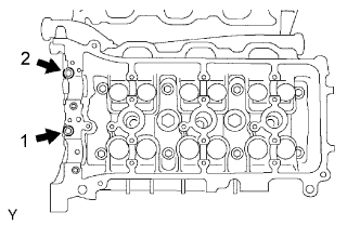 |
Using several steps, remove the 2 cylinder head bolts on the cylinder head in the sequence as shown in the illustration.
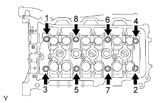 |
Using several steps, loosen the 8 cylinder head bolts on the cylinder head uniformly with a 10 mm bi-hexagon wrench in the sequence as shown in the illustration. Remove the 8 cylinder head bolts and plate washers.
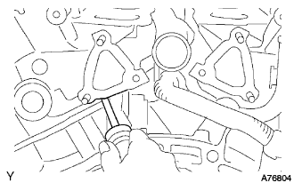 |
Lift the cylinder head from the dowels on the cylinder block, and place the cylinder head on wooden blocks on a bench.
| 28. REMOVE NO. 2 CYLINDER HEAD GASKET |