Home › Audio / Visual / Telematics › PARK ASSIST / MONITORING › TOYOTA PARKING ASSIST-SENSOR SYSTEM › from 2013.08
RM1440E _56 Audio / Visual / Telematics _056151 PARK ASSIST / MONITORING _0274043 TOYOTA PARKING ASSIST-SENSOR SYSTEM J

PARK ASSIST / MONITORING  TOYOTA PARKING ASSIST-SENSOR SYSTEM  Back Sonar Sensor LH Circuit  


DESCRIPTION

The No. 1 ultrasonic sensor sends and receives ultrasonic waves. Based on the received wave, the sensor calculates the approximate distance between the vehicle and the obstacle, and sends the distance value as a signal to the clearance warning ECU assembly.

WIRING DIAGRAM
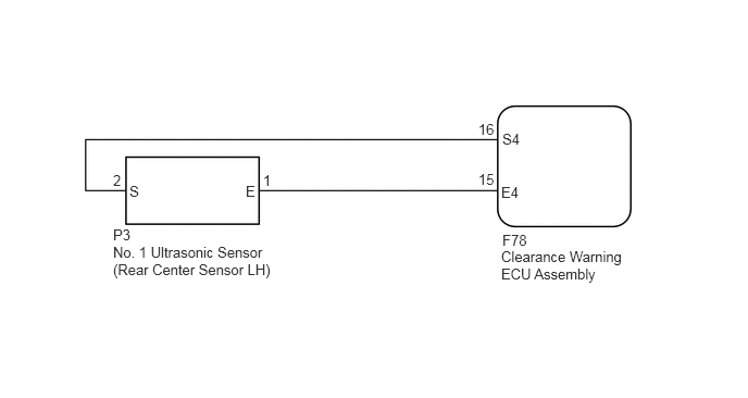
E282887E09
4.813,2.219 5.188,2.49 0.375,0.271 10 false F78 4.802,1.76 5.156,1.969 0.354,0.208 10 false E4 4.583,1.635 4.802,1.844 0.219,0.208 10 false 15 4.813,1.25 5.188,1.521 0.375,0.271 10 false S4 2.354,1.75 2.729,2.021 0.375,0.271 10 false E 1.24,1.75 1.615,2.021 0.375,0.271 10 false S 4.583,1.156 4.802,1.365 0.219,0.208 10 false 16 2.521,1.646 2.74,1.854 0.219,0.208 10 false 1 1.083,1.646 1.302,1.854 0.219,0.208 10 false 2 4.802,2.375 6.229,2.792 1.427,0.417 10 false Clearance Warning ECU Assembly 1.083,2.167 1.458,2.438 0.375,0.271 10 false P3 1.083,2.333 2.708,2.75 1.625,0.417 10 false No. 1 Ultrasonic Sensor (Rear Center Sensor LH)

PROCEDURE

1.INSPECT NO. 1 ULTRASONIC SENSOR (REAR CENTER SENSOR LH)
a.

Remove the No. 1 ultrasonic sensor (rear center sensor LH) (See page Audio / Visual / Telematics>PARK ASSIST / MONITORING>ULTRASONIC SENSOR(for Rear)>REMOVAL).


b.

Inspect the No. 1 ultrasonic sensor (rear center sensor LH) (See page Audio / Visual / Telematics>PARK ASSIST / MONITORING>ULTRASONIC SENSOR(for Rear)>INSPECTION).


OK

2.CHECK HARNESS AND CONNECTOR (REAR CENTER SENSOR LH - CLEARANCE WARNING ECU ASSEMBLY)

NG

REPLACE NO. 1 ULTRASONIC SENSOR (REAR CENTER SENSOR LH)

2.CHECK HARNESS AND CONNECTOR (REAR CENTER SENSOR LH - CLEARANCE WARNING ECU ASSEMBLY)
a.

Disconnect the P3 No. 1 ultrasonic sensor (rear center sensor LH) connector.


b.

Disconnect the F78 clearance warning ECU assembly connector.


c.

Measure the resistance according to the value(s) in the table below.

Standard Resistance:
Tester Connection Condition Specified Condition
P3-1 (E) - F78-15 (E4) Always Below 1 Ω
P3-2 (S) - F78-16 (S4) Always Below 1 Ω
P3-1 (E) - Body ground Always 10 kΩ or higher
P3-2 (S) - Body ground Always 10 kΩ or higher


OK

PROCEED TO NEXT SUSPECTED AREA SHOWN IN PROBLEM SYMPTOMS TABLE

NG

REPAIR OR REPLACE HARNESS OR CONNECTOR