LIGHTING (INT) LIGHTING SYSTEM TERMINALS OF ECU
CHECK DRIVER SIDE JUNCTION BLOCK ASSEMBLY, MAIN BODY ECU (MULTIPLEX NETWORK BODY ECU)
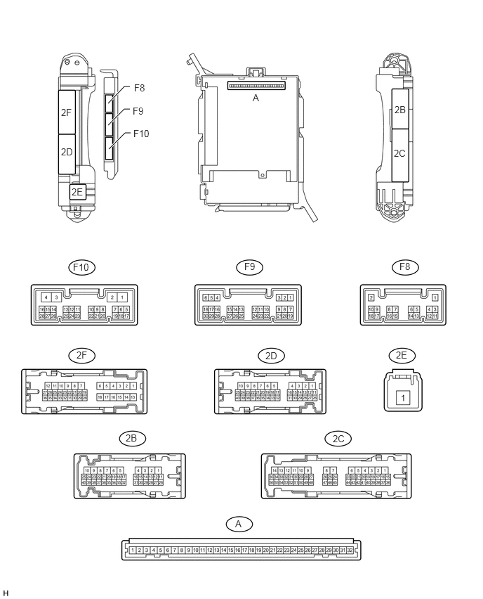
Remove the main body ECU (See page Power Source / Network>POWER DISTRIBUTION>MAIN BODY ECU>REMOVAL).
Measure the voltage and resistance according to the value(s) in the table below.
| Terminal No. (Symbol) | Wiring Color | Terminal Description | Condition | Specified Condition |
|---|---|---|---|---|
| A-29 (ACC) - Body ground | - | ACC power supply | Ignition switch ACC | 11 to 14 V |
| A-30 (BECU) - Body ground | - | Battery power supply | Always | 11 to 14 V |
| A-32 (IG) - Body ground | - | Ignition power supply | Ignition switch ON | 11 to 14 V |
| A-11 (GND1) - Body ground | - | Ground | Always | Below 1 Ω |
| F10-3 (GND2) - Body ground | W-B - Body ground | Ground | Always | Below 1 Ω |
If the result is not as specified, there may be a malfunction on the wire harness side.
Install the main body ECU (See page Power Source / Network>POWER DISTRIBUTION>MAIN BODY ECU>REMOVAL).
Measure the voltage according to the value(s) in the table below.
| Terminal No. (Symbol) | Wiring Color | Terminal Description | Condition | Specified Condition |
|---|---|---|---|---|
| F8-3 (LCTY) - 2B-4 (GND1) | V - W-B | Rear door courtesy light switch LH signal | Rear door LH open | Below 1 V |
| Rear door LH closed | 11 to 14 V | |||
| F8-5 (CSPT) - 2B-4 (GND1) | SB - W-B | Center console spot light signal | Ignition switch off | 11 to 14 V |
| Ignition switch ON or ACC | Below 1 V | |||
| F9-2 (DOMR) - 2B-4 (GND1) | V - W-B | DOME relay drive output | Battery saving control not operating | 11 to 14 V |
| Battery saving control operating | Below 1 V | |||
| F9-6 (RCTY) - 2B-4 (GND1) | R - W-B | Rear door courtesy light switch RH signal | Rear door RH open | Below 1 V |
| Rear door RH closed | 11 to 14 V | |||
| F10-4 (MILE) - 2B-4 (GND1)* | W - W-B | Door mirror foot light signal output | Door mirror foot light on | 11 to 14 V |
| Door mirror foot light off | Below 1 V | |||
| 2B-18 (ILE) - 2B-4 (GND1) | G - W-B | Interior light signal | Interior light on | Below 1 V |
| Interior light off | 11 to 14 V | |||
| 2B-15 (FRCY) - 2B-4 (GND1) | B - W-B | Front door courtesy light switch RH signal | Front door RH open | Below 1 V |
| Front door RH closed | 11 to 14 V | |||
| 2F-27 (FLCY) - 2B-4 (GND1) | R - W-B | Front door courtesy light switch LH signal | Front door LH open | Below 1 V |
| Front door LH closed | 11 to 14 V |
*: w/ Door Mirror Foot Light
If the result is not as specified, the main body ECU may have a malfunction.
CHECK MULTIPLEX NETWORK DOOR ECU
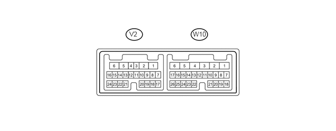
Disconnect the V2 and W10 multiplex network door ECU connectors.
Measure the voltage and resistance according to the value(s) in the table below.
| Terminal No. (Symbol) | Wiring Color | Terminal Description | Condition | Specified Condition |
|---|---|---|---|---|
| V2-17 (B1) - Body ground | R - Body ground | Battery power supply | Always | 11 to 14 V |
| V2-6 (GND) - Body ground | W-B - Body ground | Ground | Always | Below 1 Ω |
If the result is not as specified, there may be a malfunction on the wire harness side.
Reconnect the V2 and W10 multiplex network door ECU connectors.
Measure the voltage according to the value(s) in the table below.
| Terminal No. (Symbol) | Wiring Color | Terminal Description | Condition | Specified Condition |
|---|---|---|---|---|
| W10-10 (BDCY) - W10-18 (CTYE) | P - G | Back door courtesy light switch signal | Back door open | Below 1 V |
| Back door closed | Pulse generation
(See waveform 1 or 2) |
|||
| W10-22 (LGLP) - V2-6 (GND) | L - W-B | Spot light LH signal | Spot light LH on | Pulse generation
(See waveform 3) |
| Spot light LH off | Pulse generation
(See waveform 4) |
|||
| W10-23 (LGP2) - V2-6 (GND) | L - W-B | Spot light RH signal | Spot light RH on | Pulse generation
(See waveform 3) |
| Spot light RH off | Pulse generation
(See waveform 4) |
|||
| W10-25 (B2) - V2-6 (GND) | R - W-B | Battery power supply | Always | 11 to 14 V |
| W10-26 (B3) - V2-6 (GND) | R - W-B | Battery power supply | Always | 11 to 14 V |
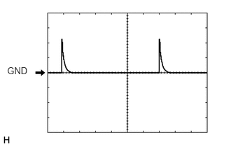
Waveform 1
| Item | Content |
|---|---|
| Terminal No. (Symbol) | W10-10 (BDCY) - W10-18 (CTYE) |
| Tool setting | 5 V/DIV., 10 ms/DIV. |
| Condition | Back door closed |
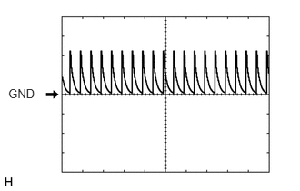
Waveform 2
| Item | Content |
|---|---|
| Terminal No. (Symbol) | W10-10 (BDCY) - W10-18 (CTYE) |
| Tool setting | 5 V/DIV., 10 ms/DIV. |
| Condition | Back door closed |
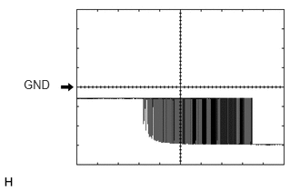
Waveform 3
| Item | Content |
|---|---|
| Terminal No. (Symbol) | W10-22 (LGLP) - V2-6 (GND)
W10-23 (LGP2) - V2-6 (GND) |
| Tool setting | 5 V/DIV., 200 ms/DIV. |
| Condition | ·
Spot light LH on ·
Spot light RH on |
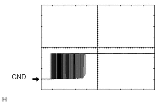
Waveform 4
| Item | Content |
|---|---|
| Terminal No. (Symbol) | W10-22 (LGLP) - V2-6 (GND)
W10-23 (LGP2) - V2-6 (GND) |
| Tool setting | 5 V/DIV., 200 ms/DIV. |
| Condition | ·
Spot light LH off ·
Spot light RH off |