Home › Vehicle Interior › METER / GAUGE / DISPLAY › METER / GAUGE SYSTEM
RM1440E _58 Vehicle Interior _056158 METER / GAUGE / DISPLAY _0274083 METER / GAUGE SYSTEM J

METER / GAUGE / DISPLAY  METER / GAUGE SYSTEM  Operating Light Control Rheostat does not Change Light Brightness  


DESCRIPTION

When the light control rheostat dial is turned upward, the combination meter and vehicle interior illumination will become brighter. When the light control rheostat dial is turned downward, the combination meter and vehicle illumination will dim.

WIRING DIAGRAM
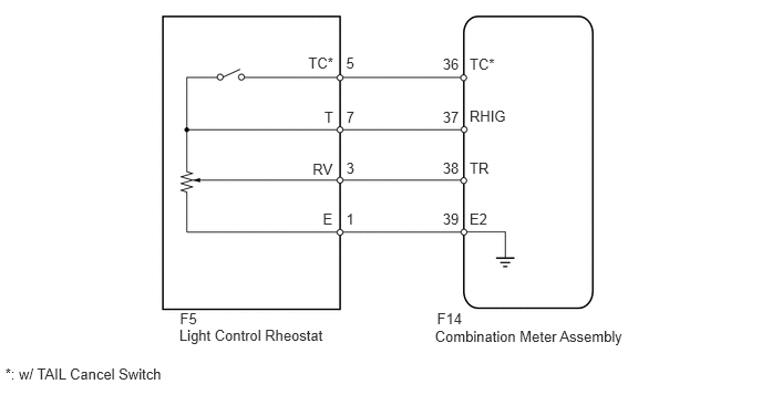
E200191E01
1.686,3.078 3.097,3.248 1.410,0.170 10 Light Control Rheostat 4.09,3.086 5.923,3.256 1.834,0.170 10 Combination Meter Assembly 4.416,1.015 4.797,1.185 0.382,0.170 10 RHIG 4.416,1.504 4.637,1.675 0.221,0.170 10 TR 4.416,1.982 4.630,2.152 0.214,0.170 10 E2 4.416,0.518 4.685,0.688 0.269,0.170 10 TC* 3.05,1.021 3.162,1.191 0.112,0.170 10 T 2.94,1.506 3.161,1.676 0.221,0.170 10 RV 3.036,1.979 3.162,2.149 0.126,0.170 10 E 4.164,0.521 4.348,0.691 0.185,0.170 10 36 4.164,1.022 4.348,1.193 0.185,0.170 10 37 4.164,1.502 4.348,1.672 0.185,0.170 10 38 4.164,1.982 4.348,2.152 0.185,0.170 10 39 3.255,0.512 3.361,0.682 0.106,0.170 10 5 3.256,1.022 3.361,1.192 0.106,0.170 10 7 3.256,1.501 3.361,1.671 0.106,0.170 10 3 3.255,1.979 3.361,2.149 0.106,0.170 10 1 4.11,2.915 4.367,3.085 0.258,0.170 10 F14 1.692,2.915 1.881,3.085 0.188,0.170 10 F5 2.899,0.51 3.168,0.680 0.269,0.170 10 TC* 0.049,3.441 1.596,3.611 1.548,0.170 10 *: w/ TAIL Cancel Switch

PROCEDURE

1.READ VALUE USING INTELLIGENT TESTER (LIGHT CONTROL RHEOSTAT)
a.

Operate the intelligent tester according to the display and select the Data List (See page Vehicle Interior>METER / GAUGE / DISPLAY>METER / GAUGE SYSTEM>DATA LIST / ACTIVE TEST).

Combination Meter
Tester Display Measurement Item/Range Normal Condition Diagnostic Note
Tail Cancel SW* TAIL cancel switch condition/ON or OFF ON: TAIL cancel switch on
OFF: TAIL cancel switch off
-
Rheostat value Light control rheostat switch input/Min.: 0, Max.: 100 Light control rheostat switch fully turned downward (0) → fully turned upward (100) Unit: %

*: w/ TAIL Cancel Switch


OK:

Light brightness can be changed within specified range by manual operation.


OK

REPLACE COMBINATION METER ASSEMBLY

NG

2.INSPECT LIGHT CONTROL RHEOSTAT

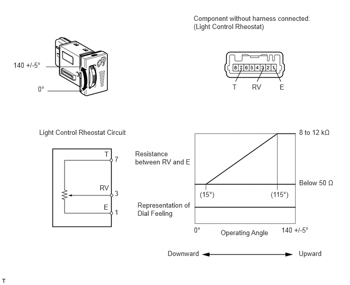
w/o TAIL Cancel Switch:

a.

Inspect the light control rheostat.

E200224E02
0.271,1.245 0.906,1.401 0.635,0.156 10 140 +/-5° 0.776,1.743 0.959,1.899 0.184,0.156 10 0° 3.964,0.296 6.465,0.646 2.501,0.350 10 Component without harness connected: (Light Control Rheostat) 4.091,3.896 4.441,4.052 0.350,0.156 10 (15°) 5.543,3.896 5.945,4.052 0.401,0.156 10 (115°) 6.125,2.63 6.802,2.791 0.677,0.161 10 8 to 12 kΩ 6.125,3.657 6.871,3.818 0.746,0.161 10 Below 50 Ω 2.767,3.062 3.951,3.392 1.184,0.330 10 Resistance between RV and E 2.816,4.113 3.965,4.443 1.149,0.330 10 Representation of Dial Feeling 3.971,4.62 4.134,4.776 0.163,0.156 10 0° 5.76,4.62 6.395,4.776 0.635,0.156 10 140 +/-5° 4.518,4.676 5.561,4.860 1.042,0.184 10 Operating Angle 3.433,5.101 4.130,5.285 0.698,0.184 10 Downward 6.116,5.101 6.626,5.285 0.510,0.184 10 Upward 5.727,1.698 5.844,1.853 0.118,0.156 10 E 5.159,1.698 5.381,1.853 0.222,0.156 10 RV 4.76,1.698 4.878,1.853 0.118,0.156 10 T 5.618,1.396 5.751,1.67 false 5.398,1.396 5.264,1.67 false 4.956,1.396 4.823,1.67 false 0.803,2.621 2.658,2.800 1.855,0.179 10 Light Control Rheostat Circuit 2.125,4.154 2.262,4.319 0.137,0.165 10 E 2.041,3.764 2.262,3.929 0.221,0.165 10 RV 2.139,3.078 2.262,3.243 0.123,0.165 10 T 2.347,4.258 2.456,4.428 0.110,0.170 10 1 2.347,3.877 2.456,4.047 0.110,0.170 10 3 2.347,3.177 2.456,3.347 0.110,0.170 10 7

i.

Remove the light control rheostat (See page Vehicle Interior>METER / GAUGE / DISPLAY>LIGHT CONTROL RHEOSTAT>REMOVAL).


ii.

Measure the resistance according to the table below.

Standard Resistance:
Tester Connection Switch Condition Specified Condition
7 (T) - 1 (E) Always 8 to 12 kΩ
3 (RV) - 1 (E) Light control rheostat fully turned upward → fully turned downward 8 to 12 kΩ → Below 50 Ω


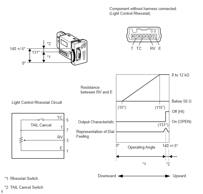
w/ TAIL Cancel Switch:

b.

Inspect the light control rheostat.

E200225E01
0.343,1.631 0.939,1.782 0.596,0.151 10 140 +/-5° 0.782,2.147 0.943,2.298 0.161,0.151 10 0° 1.126,1.762 1.439,1.913 0.313,0.151 10 131° 1.661,1.463 1.817,1.614 0.156,0.151 10 *2 1.661,1.932 1.817,2.083 0.156,0.151 10 *1 0.411,3.536 2.266,3.715 1.855,0.179 10 Light Control Rheostat Circuit 3.863,0.219 6.353,0.569 2.489,0.350 10 Component without harness connected: (Light Control Rheostat) 6.062,2.56 6.739,2.730 0.677,0.170 10 8 to 12 kΩ 6.062,3.492 6.814,3.662 0.752,0.170 10 Below 50 Ω 5.73,5.059 6.326,5.210 0.596,0.151 10 140 +/-5° 4.087,5.049 4.247,5.200 0.161,0.151 10 0° 5.571,4.326 5.991,4.477 0.420,0.151 10 (131°) 4.154,3.709 4.495,3.860 0.341,0.151 10 (15°) 5.469,3.709 5.884,3.860 0.415,0.151 10 (115°) 2.755,4.214 4.096,4.391 1.341,0.178 10 Output Characteristic 2.695,4.563 4.092,4.900 1.398,0.338 10 Representation of Dial Feeling 4.507,5.113 5.547,5.301 1.040,0.188 10 Operating Angle 5.866,5.707 6.022,5.858 0.156,0.151 10 *2 5.025,5.707 5.181,5.858 0.156,0.151 10 *1 3.456,6.13 4.162,6.318 0.706,0.188 10 Downward 6.099,6.13 6.603,6.318 0.504,0.188 10 Upward 2.846,2.997 4.042,3.340 1.195,0.343 10 Resistance between RV and E 0.159,6.527 1.627,6.678 1.468,0.151 10 *2: TAIL Cancel Switch 0.159,6.217 1.408,6.368 1.250,0.151 10 *1: Rheostat Switch 6.062,3.856 6.553,4.026 0.492,0.170 10 Off (HI) 6.062,4.204 6.824,4.373 0.762,0.170 10 On (OPEN) 5.595,1.63 5.732,1.795 0.137,0.165 10 E 5.262,1.324 5.395,1.597 false 5.296,1.63 5.517,1.795 0.221,0.165 10 RV 4.815,1.63 5.036,1.795 0.221,0.165 10 TC 4.619,1.63 4.742,1.795 0.123,0.165 10 T 5.486,1.324 5.619,1.597 false 5.04,1.324 4.907,1.597 false 4.816,1.324 4.683,1.597 false 2.111,5.146 2.248,5.312 0.137,0.165 10 E 2.027,4.763 2.248,4.929 0.221,0.165 10 RV 2.018,4.068 2.238,4.233 0.221,0.165 10 TC 2.134,4.413 2.258,4.578 0.123,0.165 10 T 2.34,5.25 2.449,5.420 0.110,0.170 10 1 2.34,4.877 2.449,5.047 0.110,0.170 10 3 2.34,4.158 2.449,4.327 0.110,0.170 10 5 2.34,4.512 2.449,4.682 0.110,0.170 10 7 1.081,4.334 1.872,4.485 0.791,0.151 10 TAIL Cancel

i.

Remove the light control rheostat (See page Vehicle Interior>METER / GAUGE / DISPLAY>LIGHT CONTROL RHEOSTAT>REMOVAL).


ii.

Measure the resistance according to the table below.

Standard Resistance:
Tester Connection Switch Condition Specified Condition
7 (T) - 5 (TC) TAIL cancel switch off → on 1 MΩ or higher → Below 1 Ω
7 (T) - 1 (E) Always 8 to 12 kΩ
3 (RV) - 1 (E) Light control rheostat fully turned upward → fully turned downward 8 to 12 kΩ → Below 50 Ω


OK

3.CHECK HARNESS AND CONNECTOR (COMBINATION METER - LIGHT CONTROL RHEOSTAT)

NG

3.CHECK HARNESS AND CONNECTOR (COMBINATION METER - LIGHT CONTROL RHEOSTAT)
a.

Disconnect the F14 meter connector.


b.

Disconnect the F5 rheostat connector.


c.

Measure the resistance according to the value(s) in the table below.

Standard Resistance:
Tester Connection Condition Specified Condition
F14-36 (TC) - F5-5 (TC)* Always Below 1 Ω
F14-37 (RHIG) - F5-7 (T)
F14-38 (TR) - F5-3 (RV)
F14-39 (E2) - F5-1 (E)


*: w/ TAIL Cancel Switch


OK

4.REPLACE COMBINATION METER ASSEMBLY

NG

REPAIR OR REPLACE HARNESS OR CONNECTOR

4.REPLACE COMBINATION METER ASSEMBLY
a.

Replace the combination meter assembly with a new or normally functioning one. Perform an operation inspection.

OK:

Combination meter assembly operates normally.


OK

END

NG