RM1440E
_58
Vehicle Interior
_056158
METER / GAUGE / DISPLAY
_0274083
METER / GAUGE SYSTEM
J
METER / GAUGE / DISPLAY METER / GAUGE SYSTEM Accessory Meter does not Illuminate
DESCRIPTION
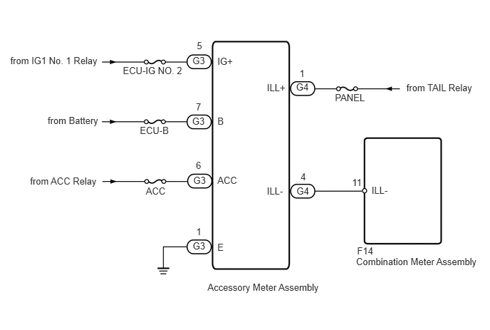
This circuit provides power to the accessory meter assembly.
WIRING DIAGRAM
0.151,0.801 1.476,0.957
1.325,0.156
10
from IG1 No. 1 Relay
0.697,1.681 1.480,1.837
0.784,0.156
10
from Battery
0.44,2.562 1.478,2.718
1.039,0.156
10
from ACC Relay
2.045,1.818 2.504,1.974
0.459,0.156
10
ECU-B
1.797,0.946 2.725,1.101
0.928,0.156
10
ECU-IG NO. 2
3.18,1.686 3.297,1.842
0.117,0.156
10
B
3.18,0.816 3.430,0.972
0.250,0.156
10
IG+
3.18,2.557 3.506,2.711
0.326,0.154
10
ACC
3.18,3.528 3.297,3.684
0.117,0.156
10
E
2.865,1.483 2.982,1.639
0.117,0.156
10
7
2.879,0.587 2.997,0.743
0.117,0.156
10
5
2.865,2.337 2.982,2.493
0.117,0.156
10
6
2.87,3.307 2.987,3.463
0.117,0.156
10
1
4.38,0.987 4.497,1.143
0.117,0.156
10
1
4.396,2.495 4.513,2.651
0.117,0.156
10
4
5.944,1.2 6.997,1.356
1.054,0.156
10
from TAIL Relay
5.208,3.739 7.051,3.901
1.843,0.162
10
Combination Meter Assembly
5.223,3.58 5.509,3.734
0.286,0.154
10
F14
3.035,4.116 4.747,4.278
1.712,0.162
10
Accessory Meter Assembly
2.133,2.704 2.457,2.860
0.323,0.156
10
ACC
4.899,1.349 5.374,1.505
0.475,0.156
10
PANEL
2.815,0.799 3.034,0.955
0.220,0.156
10
G3
2.811,1.685 3.031,1.841
0.220,0.156
10
G3
2.827,2.555 3.047,2.711
0.220,0.156
10
G3
2.819,3.51 3.039,3.666
0.220,0.156
10
G3
4.331,1.19 4.551,1.346
0.220,0.156
10
G4
4.337,2.705 4.556,2.861
0.220,0.156
10
G4
5.149,2.586 5.344,2.742
0.195,0.156
10
11
3.904,1.196 4.203,1.352
0.299,0.156
10
ILL+
3.904,2.711 4.203,2.866
0.299,0.156
10
ILL-
5.435,2.698 5.734,2.854
0.299,0.156
10
ILL-
PROCEDURE
1.CHECK ACCESSORY METER ASSEMBLY
a.
Check the type of accessory meter assembly malfunction.
| Result | Proceed to |
|---|---|
| Accessory meter assembly does not display at all | A |
| Accessory meter assembly does not dim at night | B |
A
2.CHECK HARNESS AND CONNECTOR (ACCESSORY METER ASSEMBLY CIRCUIT)
B
3.CHECK HARNESS AND CONNECTOR (ACCESSORY METER ASSEMBLY - COMBINATION METER ASSEMBLY)
2.CHECK HARNESS AND CONNECTOR (ACCESSORY METER ASSEMBLY CIRCUIT)
a.
1.602,0.244 1.827,0.397
0.224,0.153
10
G3
1.084,1.559 0.813,2.058
false
2.673,2.081 2.810,2.235
0.136,0.154
10
B
2.002,1.44 2.294,0.401
2.294,0.401 2.403,0.401
false
2.447,0.287 2.778,0.445
0.331,0.158
10
ACC
1.816,1.567 1.82,2.072
false
1.728,2.086 1.994,2.232
0.266,0.146
10
IG+
2.219,1.544 2.7,2.073
false
0.749,2.085 0.885,2.233
0.136,0.148
10
E
0.13,0.066 0.305,0.218
0.175,0.153
10
*a
1.597,2.771 1.821,2.924
0.224,0.153
10
G4
1.426,3.84 1.018,4.201
false
0.954,4.228 1.271,4.376
0.317,0.148
10
ILL+
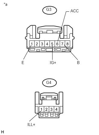
Disconnect the G3 and G4 accessory meter connectors.
b.
Measure the voltage according to the value(s) in the table below.
- Standard Voltage:
Tester Connection Switch Condition Specified Condition G3-5 (IG+) - Body ground Ignition switch ON 11 to 14 V G3-6 (ACC) - Body ground Ignition switch ACC 11 to 14 V G3-7 (B) - Body ground Always 11 to 14 V G4-1 (ILL+) - Body ground Light control switch TAIL or HEAD 11 to 14 V
c.
Measure the resistance according to the value(s) in the table below.
- Standard Resistance:
Tester Connection Condition Specified Condition G3-1 (E) - Body ground Always Below 1 Ω
| *a | Front view of wire harness connector
(to Accessory Meter) |
OK
REPLACE ACCESSORY METER ASSEMBLY
NG
REPAIR OR REPLACE HARNESS OR CONNECTOR
3.CHECK HARNESS AND CONNECTOR (ACCESSORY METER ASSEMBLY - COMBINATION METER ASSEMBLY)
a.
Disconnect the F14 meter connector.
b.
Disconnect the G4 accessory meter connector.
c.
Measure the resistance according to the value(s) in the table below.
- Standard Resistance:
Tester Connection Condition Specified Condition G4-4 (ILL-) - F14-11 (ILL-) Always Below 1 Ω G4-4 (ILL-) - Body ground Always 10 kΩ or higher
OK
4.REPLACE ACCESSORY METER ASSEMBLY
NG
REPAIR OR REPLACE HARNESS OR CONNECTOR
4.REPLACE ACCESSORY METER ASSEMBLY
a.
Replace the accessory meter assembly with a new or normally functioning one (See page Vehicle Interior>METER / GAUGE / DISPLAY>ACCESSORY METER>REMOVAL).
- OK:
The operation of the accessory meter assembly returns to normal.
OK
END
NG
REPLACE COMBINATION METER ASSEMBLY