RM1440E
_58
Vehicle Interior
_056163
HEATING / AIR CONDITIONING
_0274151
AIR CONDITIONING SYSTEM(for Automatic Air Conditioning System)
C
HEATING / AIR CONDITIONING AIR CONDITIONING SYSTEM(for Automatic Air Conditioning System) B1497/97 BUS IC Communication Malfunction
DESCRIPTION
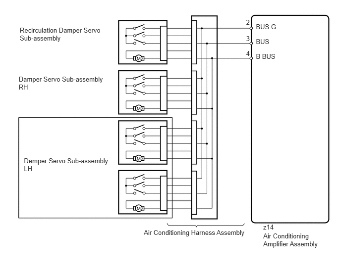
The air conditioning harness assembly connects the air conditioning amplifier assembly and each servo motor. The air conditioning amplifier assembly supplies power and sends operation instructions to each servo motor through the air conditioning harness assembly. Each servo motor sends the damper position information to the air conditioning amplifier assembly.
| DTC Code | DTC Detection Condition | Trouble Area |
|---|---|---|
| B1497/97 | An open circuit or malfunction in the communication line. | ·
Air conditioning harness assembly ·
Air conditioning amplifier assembly |
WIRING DIAGRAM
0.416,0.549 2.227,0.942
1.811,0.392
10
Recirculation Damper Servo Sub-assembly
3.022,4.811 5.291,5.044
2.269,0.232
10
Air Conditioning Harness Assembly
5.532,4.882 6.864,5.225
1.332,0.343
10
Air Conditioning Amplifier Assembly
5.379,0.482 5.963,0.636
0.584,0.154
10
BUS G
5.379,0.79 5.806,0.944
0.427,0.154
10
BUS
5.379,1.105 5.862,1.259
0.482,0.154
10
B BUS
5.532,4.702 5.806,4.855
0.274,0.154
10
z14
5.172,0.388 5.285,0.542
0.113,0.154
10
2
5.172,0.732 5.285,0.885
0.113,0.154
10
3
5.172,1.04 5.285,1.194
0.113,0.154
10
4
0.393,1.584 2.278,1.946
1.885,0.362
10
Damper Servo Sub-assembly RH
0.503,3.303 2.351,3.667
1.848,0.364
10
Damper Servo Sub-assembly LH
PROCEDURE
1.CHECK AIR CONDITIONING AMPLIFIER ASSEMBLY
a.
2.823,1.792 3.156,2.594
false
2.719,1.813 2.427,2.521
true
2.615,1.813 1.938,2.771
true
2.552,0.646 2.823,0.813
0.271,0.167
10
false
z14
0.083,0.052 0.292,0.26
0.208,0.208
10
false
*a
2.896,2.625 3.365,2.792
0.469,0.167
10
false
BUS G
2.25,2.563 2.573,2.729
0.323,0.167
10
false
BUS
1.667,2.823 2.167,2.99
0.5,0.167
10
false
B BUS
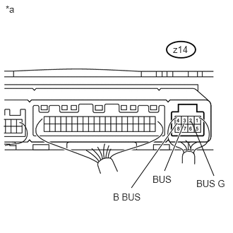
Remove the air conditioning amplifier assembly with its connectors still connected (See page Vehicle Interior>HEATING / AIR CONDITIONING>AIR CONDITIONING AMPLIFIER>REMOVAL).
b.
Measure the resistance according to the value(s) in the table below.
- Standard Resistance:
Tester Connection Condition Specified Condition z14-2 (BUS G) - Body ground Always Below 1 Ω
c.
Measure the voltage according to the value(s) in the table below.
- Standard Voltage:
Tester Connection Switch Condition Specified Condition z14-2 (BUS G) - z14-4 (B BUS) Always 11 to 14 V z14-2 (BUS G) - z14-3 (BUS) Ignition switch ON Pulse generation
| *a | Component with harness connected
(Air Conditioning Amplifier Assembly) |
| Result | Proceed to |
|---|---|
| OK (When troubleshooting according to problem symptoms table) | A |
| OK (When troubleshooting according to the DTC) | B |
| NG | C |
A
PROCEED TO NEXT SUSPECTED AREA SHOWN IN PROBLEM SYMPTOMS TABLE
B
REPLACE AIR CONDITIONING HARNESS ASSEMBLY
C
REPLACE AIR CONDITIONING AMPLIFIER ASSEMBLY