RM1440E
_59
Vehicle Exterior
_056167
SLIDING ROOF / CONVERTIBLE
_0274174
SLIDING ROOF SYSTEM
J
SLIDING ROOF / CONVERTIBLE SLIDING ROOF SYSTEM Sliding Roof ECU Power Source Circuit
DESCRIPTION
If the sliding function and tilt function do not operate, there may be a malfunction in the sliding roof drive gear sub-assembly power source circuit.
WIRING DIAGRAM
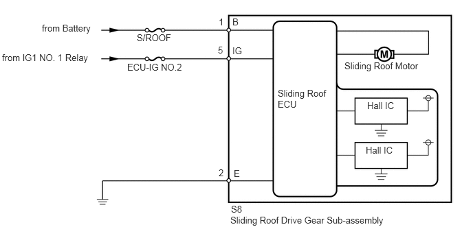
0.635,0.344 1.688,0.656
1.052,0.313
10
from Battery
2.073,0.49 2.823,0.813
0.75,0.323
10
S/ROOF
0.031,0.792 1.802,1.229
1.771,0.438
10
from IG1 NO. 1 Relay
1.927,0.938 2.958,1.479
1.031,0.542
10
ECU-IG NO.2
4.208,1.333 5.031,2.229
0.823,0.896
10
Sliding Roof ECU
5.219,0.917 6.813,1.271
1.594,0.354
10
Sliding Roof Motor
3.49,3.26 6.729,3.698
3.24,0.438
10
Sliding Roof Drive Gear Sub-assembly
5.563,1.521 6.177,1.917
0.615,0.396
10
Hall IC
5.542,2.198 6.365,2.719
0.823,0.521
10
Hall IC
3.313,0.25 3.552,0.438
0.24,0.188
10
1
3.302,0.677 3.573,0.979
0.271,0.302
10
5
3.521,0.25 3.823,0.552
0.302,0.302
10
B
3.5,3.094 3.813,3.302
0.313,0.208
10
S8
3.521,0.688 3.854,1.052
0.333,0.365
10
IG
3.313,2.542 3.615,2.833
0.302,0.292
10
2
3.542,2.552 4.042,2.969
0.5,0.417
10
E
CAUTION / NOTICE / HINT
- NOTICE:
- ·
When the sliding roof drive gear sub-assembly is removed and reinstalled or replaced, the sliding roof drive gear sub-assembly must be initialized (See page Vehicle Exterior>SLIDING ROOF / CONVERTIBLE>SLIDING ROOF SYSTEM>INITIALIZATION).
·Inspect the fuses for circuits related to this system before performing the following inspection procedure.
PROCEDURE
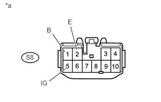
1.CHECK HARNESS AND CONNECTOR (SLIDING ROOF ECU - BATTERY AND BODY GROUND)
1.125,0.729 1.385,1.115
true
1.51,0.573 1.635,1.073
true
1.406,1.469 1.052,1.74
true
0.115,0.031 0.344,0.219
0.229,0.188
10
false
*a
0.552,1.146 0.823,1.333
0.271,0.188
10
false
S8
1,0.563 1.146,0.75
0.146,0.188
10
false
B
1.448,0.385 1.594,0.573
0.146,0.188
10
false
E
0.865,1.698 1.125,1.885
0.26,0.188
10
false
IG
a.
Disconnect the S8 ECU connector.
b.
Measure the resistance and voltage according to the value(s) in the table below.
- Standard Resistance:
Tester Connection Condition Specified Condition S8-2 (E) - Body ground Always Below 1 Ω
- Standard Voltage:
Tester Connection Switch Condition Specified Condition S8-1 (B) - Body ground Always 11 to 14 V S8-5 (IG) - Body ground Ignition switch off Below 1 V S8-5 (IG) - Body ground Ignition switch ON 11 to 14 V
| *a | Front view of wire harness connector
(to Sliding Roof Drive Gear Sub-assembly) |
OK
REPLACE SLIDING ROOF DRIVE GEAR SUB-ASSEMBLY
NG
REPAIR OR REPLACE HARNESS OR CONNECTOR