NETWORKING LIN COMMUNICATION SYSTEM TERMINALS OF ECU
CHECK MAIN BODY ECU (MULTIPLEX NETWORK BODY ECU) AND DRIVER SIDE JUNCTION BLOCK ASSEMBLY
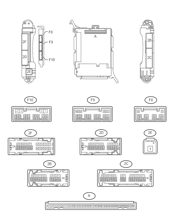
Remove the main body ECU (multiplex network body ECU) from the driver side junction block assembly (See page Power Source / Network>POWER DISTRIBUTION>MAIN BODY ECU>REMOVAL).
Measure the resistance and voltage according to the value(s) in the table below.
| Terminal No. (Symbol) | Wiring Color | Terminal Description | Condition | Specified Condition |
|---|---|---|---|---|
| F10-3 (GND2) - Body ground | W-B - Body ground | Ground | Always | Below 1 Ω |
| A-11 (GND1) - Body ground | None - Body ground | Ground | Always | Below 1 Ω |
| A-30 (BECU) - Body ground | None - Body ground | Battery power supply | Always | 11 to 14 V |
| A-32 (IG) - Body ground | None - Body ground | IG power supply | Ignition switch ON | 11 to 14 V |
If the result is not as specified, there may be a malfunction on the wire harness side.
CHECK MULTIPLEX NETWORK MASTER SWITCH ASSEMBLY
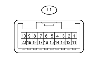
Disconnect the h1 multiplex network master switch assembly connector.
Measure the resistance and voltage according to the value(s) in the table below.
| Terminal No. (Symbol) | Wiring Color | Terminal Description | Condition | Specified Condition |
|---|---|---|---|---|
| h1-12 (GND) - Body ground | W-B - Body ground | Ground | Always | Below 1 Ω |
| h1-11 (B) - Body ground | G - Body ground | Battery power supply | Always | 11 to 14 V |
If the result is not as specified, there may be a malfunction on the wire harness side.
CHECK FRONT POWER WINDOW REGULATOR MOTOR ASSEMBLY LH
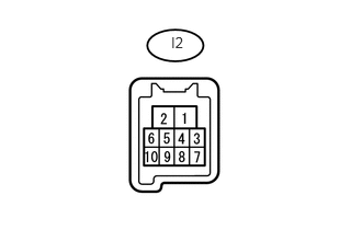
Disconnect the I2 front power window regulator motor assembly LH connector.
Measure the resistance and voltage according to the value(s) in the table below.
| Terminal No. (Symbol) | Wiring Color | Terminal Description | Condition | Specified Condition |
|---|---|---|---|---|
| I2-1 (GND) - Body ground | W-B - Body ground | Ground | Always | Below 1 Ω |
| I2-2 (B) - Body ground | R - Body ground | Battery power supply | Always | 11 to 14 V |
If the result is not as specified, there may be a malfunction on the wire harness side.
CHECK FRONT POWER WINDOW REGULATOR MOTOR ASSEMBLY RH
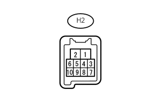
Disconnect the H2 front power window regulator motor assembly RH connector.
Measure the resistance and voltage according to the value(s) in the table below.
| Terminal No. (Symbol) | Wiring Color | Terminal Description | Condition | Specified Condition |
|---|---|---|---|---|
| H2-1 (GND) - Body ground | W-B - Body ground | Ground | Always | Below 1 Ω |
| H2-2 (B) - Body ground | G - Body ground | Battery power supply | Always | 11 to 14 V |
If the result is not as specified, there may be a malfunction on the wire harness side.
CHECK REAR POWER WINDOW REGULATOR MOTOR ASSEMBLY LH
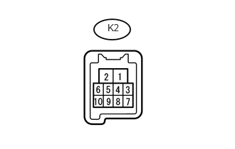
Disconnect the K2 rear power window regulator motor assembly LH connector.
Measure the resistance and voltage according to the value(s) in the table below.
| Terminal No. (Symbol) | Wiring Color | Terminal Description | Condition | Specified Condition |
|---|---|---|---|---|
| K2-1 (GND) - Body ground | W-B - Body ground | Ground | Always | Below 1 Ω |
| K2-2 (B) - Body ground | W - Body ground | Battery power supply | Always | 11 to 14 V |
If the result is not as specified, there may be a malfunction on the wire harness side.
CHECK REAR POWER WINDOW REGULATOR MOTOR ASSEMBLY RH
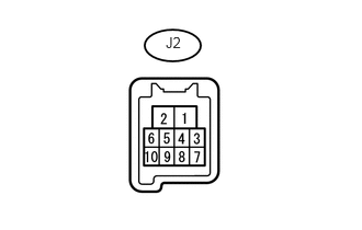
Disconnect the J2 rear power window regulator motor assembly RH connector.
Measure the resistance and voltage according to the value(s) in the table below.
| Terminal No. (Symbol) | Wiring Color | Terminal Description | Condition | Specified Condition |
|---|---|---|---|---|
| J2-1 (GND) - Body ground | W-B - Body ground | Ground | Always | Below 1 Ω |
| J2-2 (B) - Body ground | W - Body ground | Battery power supply | Always | 11 to 14 V |
If the result is not as specified, there may be a malfunction on the wire harness side.
CHECK SLIDING ROOF ECU (SLIDING ROOF DRIVE GEAR SUB-ASSEMBLY) (w/ Sliding Roof System)
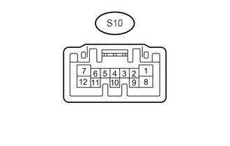
Disconnect the S10 sliding roof ECU (sliding roof drive gear sub-assembly) connector.
Measure the resistance and voltage according to the value(s) in the table below.
| Terminal No. (Symbol) | Wiring Color | Terminal Description | Condition | Specified Condition |
|---|---|---|---|---|
| S10-12 (E) - Body ground | W-B - Body ground | Ground | Always | Below 1 Ω |
| S10-8 (B) - Body ground | W - Body ground | Battery power supply | Always | 11 to 14 V |
| S10-1 (IG) - Body ground | L - Body ground | IG power supply | Ignition switch ON | 11 to 14 V |
If the result is not as specified, there may be a malfunction on the wire harness side.
CHECK AIR CONDITIONING AMPLIFIER ASSEMBLY

Disconnect the F42 air conditioning amplifier assembly connector.
Measure the resistance and voltage according to the value(s) in the table below.
| Terminal No. (Symbol) | Wiring Color | Terminal Description | Condition | Specified Condition |
|---|---|---|---|---|
| F42-14 (GND) - Body ground | W-B - Body ground | Ground | Always | Below 1 Ω |
| F42-1 (IG+) - Body ground | L - Body ground | IG power supply | Ignition switch ON | 11 to 14 V |
| F42-21 (B) - Body ground | V - Body ground | Battery power supply | Always | 11 to 14 V |
If the result is not as specified, there may be a malfunction on the wire harness side.
CHECK HEATER CONTROL ASSEMBLY
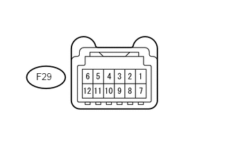
Disconnect the F29 heater control assembly connector.
Measure the resistance and voltage according to the value(s) in the table below.
| Terminal No. (Symbol) | Wiring Color | Terminal Description | Condition | Specified Condition |
|---|---|---|---|---|
| F29-11 (GND) - Body ground | W-B - Body ground | Ground | Always | Below 1 Ω |
| F29-4 (IG+) - Body ground | L - Body ground | IG power supply | Ignition switch ON | 11 to 14 V |
If the result is not as specified, there may be a malfunction on the wire harness side.
CHECK MULTIPLEX NETWORK DOOR ECU (BACK DOOR P/W)
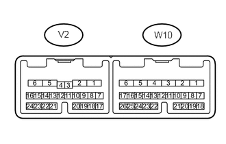
Disconnect the V2 multiplex network door ECU (back door P/W) connector.
Measure the resistance and voltage according to the value(s) in the table below.
| Terminal No. (Symbol) | Wiring Color | Terminal Description | Condition | Specified Condition |
|---|---|---|---|---|
| V2-6 (GND) - Body ground | W-B - Body ground | Ground | Always | Below 1 Ω |
| V2-7 (BECU) - Body ground | L - Body ground | Battery power supply | Always | 11 to 14 V |
| V2-8 (SIG) - Body ground | G - Body ground | IG power supply | Ignition switch ON | 11 to 14 V |
If the result is not as specified, there may be a malfunction on the wire harness side.
CHECK BACK DOOR POWER WINDOW REGULATOR MOTOR ASSEMBLY
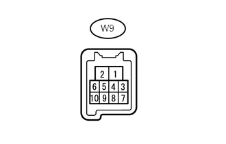
Disconnect the W9 back door power window regulator motor assembly connector.
Measure the resistance and voltage according to the value(s) in the table below.
| Terminal No. (Symbol) | Wiring Color | Terminal Description | Condition | Specified Condition |
|---|---|---|---|---|
| W9-1 (GND) - Body ground | LG - Body ground | Ground | Always | Below 1 Ω |
| W9-2 (B) - Body ground | GR - Body ground | Battery power supply | Always | 11 to 14 V |
If the result is not as specified, there may be a malfunction on the wire harness side.