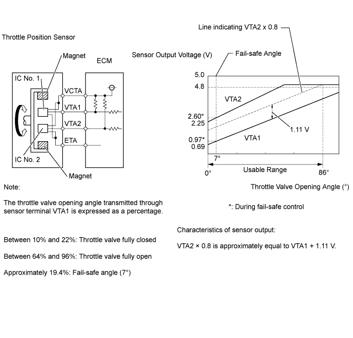
DTC P0120 Throttle / Pedal Position Sensor / Switch "A" Circuit Malfunction |
DTC P0121 Throttle / Pedal Position Sensor / Switch "A" Circuit Range / Performance Problem |
DTC P0122 Throttle / Pedal Position Sensor / Switch "A" Circuit Low Input |
DTC P0123 Throttle / Pedal Position Sensor / Switch "A" Circuit High Input |
DTC P0220 Throttle / Pedal Position Sensor / Switch "B" Circuit |
DTC P0222 Throttle / Pedal Position Sensor / Switch "B" Circuit Low Input |
DTC P0223 Throttle / Pedal Position Sensor / Switch "B" Circuit High Input |
DTC P2135 Throttle / Pedal Position Sensor / Switch "A" / "B" Voltage Correlation |
| DTC No. | DTC Detection Condition | Trouble Area |
| P0120 | Output voltage of VTA1 quickly fluctuates beyond the lower and upper malfunction thresholds for 2 seconds when the accelerator pedal is depressed (1 trip detection logic). |
|
| P0121 | Difference between VTA1 and VTA2 voltages is less than 0.8 V, or more than 1.6 V for 2 seconds (1 trip detection logic). |
|
| P0122 | Output voltage of VTA1 is 0.2 V or less for 2 seconds when the accelerator pedal is depressed (1 trip detection logic). |
|
| P0123 | Output voltage of VTA1 is 4.54 V or higher for 2 seconds when the accelerator pedal is depressed (1 trip detection logic). |
|
| P0220 | Output voltage of VTA2 quickly fluctuates beyond the lower and upper malfunction thresholds for 2 seconds when the accelerator pedal is depressed (1 trip detection logic). |
|
| P0222 | Output voltage of VTA2 is 1.75 V or less for 2 seconds when the accelerator pedal is depressed (1 trip detection logic). |
|
| P0223 | Output voltage of VTA2 is 4.8 V or higher, and VTA1 is between 0.2 V and 2.02 V for 2 seconds when the accelerator pedal is depressed (1 trip detection logic). |
|
| P2135 | Either condition is met (1 trip detection logic): (a) Difference between the output voltages of VTA1 and VTA2 is 0.02 V or less for 0.5 seconds or more. (b) Output voltage of VTA1 is 0.2 V or less, and VTA2 is 1.75 V or less for 0.4 seconds or more. |
|
| Tester Display | Accelerator Pedal Fully Released | Accelerator Pedal Fully Depressed |
| Throttle Position No.1 | 0.5 to 1.1 V | 3.3 to 4.9 V |
| Throttle Position No.2 | 2.1 to 3.1 V | 4.6 to 5.0 V |
| Related DTCs | P0120: Throttle position sensor 1 range check (Fluctuating) P0121: Throttle position sensor rationality P0122: Throttle position sensor 1 range check (Low voltage) P0123: Throttle position sensor 1 range check (High voltage) P0220: Throttle position sensor 2 range check (Fluctuating) P0222: Throttle position sensor 2 range check (Low voltage) P0223: Throttle position sensor 2 range check (High voltage) P2135: Throttle position sensor range check (Correlation) |
| Required Sensors/Components (Main) | Throttle position sensor |
| Required Sensors/Components (Related) | - |
| Frequency of Operation | Continuous |
| Duration | 2 seconds: P0120, P0121, P0122, P0123, P0220, P0222 and P0223 0.5 seconds: P2135 Case 1 0.4 seconds: P2135 Case 2 |
| MIL Operation | Immediate |
| Sequence of Operation | None |
| Monitor runs whenever following DTCs not present | None |
| Either of following conditions A or B met | - |
| A. Ignition switch ON | 0.012 seconds or more |
| B. Electronic throttle actuator power | ON |
| Monitor runs whenever following DTCs not present | P0120, P0122, P0123, P0220, P0222, P0223, P2135 (Throttle Position Sensor) |
| Either of following conditions A or B met | - |
| A. Ignition switch | ON |
| B. Electronic throttle actuator power | ON |
| VTA1 voltage | 0.2 V or less, or 4.54 V or higher |
| Difference in voltage between VTA1 and VTA2 TP sensor 1 - [TP sensor 2 x 0.8 (corrected by learning value)] | Less than 0.8 V, or more than 1.6 V |
| VTA1 voltage | 0.2 V or less |
| VTA1 voltage | 4.54 V or higher |
| Either of following conditions A or B met | - |
| A. VTA2 voltage | 1.75 V or less |
| B. All of the following conditions are met | - |
| VTA2 voltage | 4.8 V or higher |
| VTA1 voltage | 0.2 to 2.02 V |
| VTA2 voltage | 1.75 V or less |
| VTA2 voltage when VTA1 is 0.2 V or higher and 2.02 V or less | 4.8 V or higher |
| Difference between VTA1 and VTA2 voltages | 0.02 V or less |
| VTA1 voltage | 0.2 V or less |
| VTA2 voltage | 1.75 V or less |
| VTA1 voltage | 0.2 to 4.54 V |
| VTA2 voltage | 1.75 to 4.8 V |
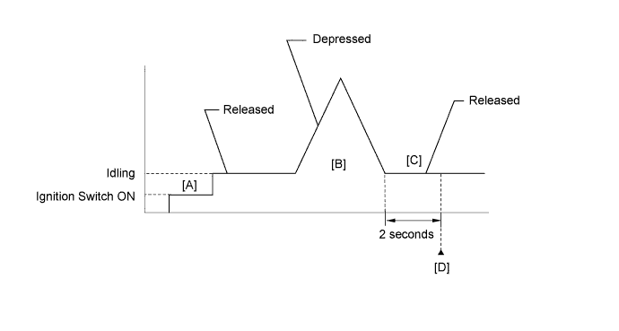
| Tester Display | Description |
| NORMAL |
|
| ABNORMAL |
|
| INCOMPLETE |
|
| N/A |
|
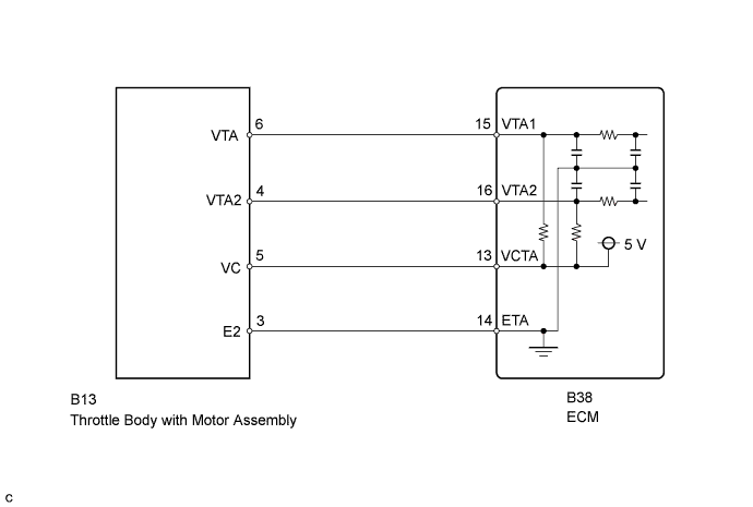
| 1.READ VALUE USING TECHSTREAM (THROTTLE POSITION NO.1 AND NO.2) |
Connect the Techstream to the DLC3.
Turn the ignition switch to ON and turn the Techstream on.
Enter the following menus: Powertrain / Engine and ECT / Data List / Throttle Position No.1 and Throttle Position No.2.
Check the values displayed on the Techstream.
| When Accelerator Pedal Released | When Accelerator Pedal Depressed | Trouble Area | Proceed to | ||
| Throttle Position No.1 | Throttle Position No.2 | Throttle Position No.1 | Throttle Position No.2 | ||
| 0 to 0.2 V | 0 to 0.2 V | 0 to 0.2 V | 0 to 0.2 V | VC circuit open | A |
| 4.5 to 5.0 V | 4.5 to 5.0 V | 4.5 to 5.0 V | 4.5 to 5.0 V | ETA circuit open | |
| 0 to 0.2 V, or 4.5 to 5.0 V | 2.4 to 3.4 V (Fail-safe) | 0 to 0.2 V, or 4.5 to 5.0 V | 2.4 to 3.4 V (Fail-safe) | VTA1 circuit open or ground short | |
| 0.7 to 1.3 V (Fail-safe) | 0 to 0.2 V, or 4.5 to 5.0 V | 0.7 to 1.3 V (Fail-safe) | 0 to 0.2 V, or 4.5 to 5.0 V | VTA2 circuit open or ground short | |
| 0.5 to 1.1 V | 2.1 to 3.1 V | 3.3 to 4.9 V (Not fail-safe) | 4.6 to 5.0 V (Not fail-safe) | TP sensor circuit normal | B |
|
| ||||
| A | |
 |
| 2.CHECK HARNESS AND CONNECTOR (THROTTLE POSITION SENSOR - ECM) |
Disconnect the throttle body with motor assembly connector.
Disconnect the ECM connector.
Measure the resistance according to the value(s) in the table below.
| Tester Connection | Condition | Specified Condition |
| B13-5 (VC) - B38-13 (VCTA) | Always | Below 1 Ω |
| B13-6 (VTA) - B38-15 (VTA1) | Always | Below 1 Ω |
| B13-4 (VTA2) - B38-16 (VTA2) | Always | Below 1 Ω |
| B13-3 (E2) - B38-14 (ETA) | Always | Below 1 Ω |
| B13-5 (VC) or B38-13 (VCTA) - Body ground | Always | 10 kΩ or higher |
| B13-6 (VTA) or B38-15 (VTA1) - Body ground | Always | 10 kΩ or higher |
| B13-4 (VTA2) or B38-16 (VTA2) - Body ground | Always | 10 kΩ or higher |
Reconnect the throttle body with motor assembly connector.
Reconnect the ECM connector.
|
| ||||
| OK | |
|
| 3.INSPECT ECM (VC VOLTAGE) |
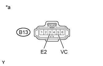 |
Disconnect the throttle body with motor assembly connector.
Turn the ignition switch to ON.
Measure the voltage according to the value(s) in the table below.
| Tester Connection | Switch Condition | Specified Condition |
| B13-5 (VC) - B13-3 (E2) | Ignition switch ON | 4.5 to 5.5 V |
| *a | Front view of wire harness connector (to Throttle Body with Motor Assembly) |
Reconnect the throttle body with motor assembly connector.
|
| ||||
| OK | |
|
| 4.REPLACE THROTTLE BODY WITH MOTOR ASSEMBLY |
Replace the throttle body with motor assembly (Click here).
| NEXT | |
|
| 5.CHECK WHETHER DTC OUTPUT RECURS (THROTTLE POSITION SENSOR DTCS) |
Connect the Techstream to the DLC3.
Turn the ignition switch to ON and turn the Techstream on.
Clear DTCs (Click here).
Start the engine.
Drive the vehicle in accordance with the driving pattern described in Confirmation Driving Pattern.
Read the output DTCs.
| Display (DTC Output) | Proceed to |
| P0120, P0121, P0122, P0123, P0220, P0222, P0223 and/or P2135 is output | A |
| No DTC is output | B |
|
| ||||
| A | ||
 | ||
| ||

