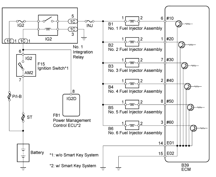
SFI SYSTEM > Fuel Injector Circuit |
| 1.CHECK FUEL INJECTOR ASSEMBLY (POWER SOURCE) |
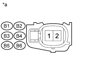 |
Disconnect the fuel injector assembly connector.
Turn the ignition switch ON.
Measure the voltage according to the value(s) in the table below.
| Cylinder | Tester Connection | Switch Condition | Specified Condition |
| No. 1 | B1-1 - Body ground | Ignition switch ON | 11 to 14 V |
| No. 2 | B2-1 - Body ground | Ignition switch ON | 11 to 14 V |
| No. 3 | B3-1 - Body ground | Ignition switch ON | 11 to 14 V |
| No. 4 | B4-1 - Body ground | Ignition switch ON | 11 to 14 V |
| No. 5 | B5-1 - Body ground | Ignition switch ON | 11 to 14 V |
| No. 6 | B6-1 - Body ground | Ignition switch ON | 11 to 14 V |
| *a | Front view of wire harness connector (to Fuel Injector Assembly) |
Turn the ignition switch off.
Reconnect the fuel injector assembly connector.
|
| ||||
| OK | |
 |
| 2.INSPECT FUEL INJECTOR ASSEMBLY |
Inspect the fuel injector assembly (Click here).
|
| ||||
| OK | |
|
| 3.CHECK HARNESS AND CONNECTOR (FUEL INJECTOR ASSEMBLY - ECM) |
Disconnect the fuel injector assembly connector.
Disconnect the ECM connector.
Measure the resistance according to the value(s) in the table below.
| Cylinder | Tester Connection | Condition | Specified Condition |
| No. 1 | B1-2 - Body ground | Always | 10 kΩ or higher |
| B1-2 - B39-6 (#10) | Always | Below 1 Ω | |
| No. 2 | B2-2 - Body ground | Always | 10 kΩ or higher |
| B2-2 - B39-1 (#20) | Always | Below 1 Ω | |
| No. 3 | B3-2 - Body ground | Always | 10 kΩ or higher |
| B3-2 - B39-7 (#30) | Always | Below 1 Ω | |
| No. 4 | B4-2 - Body ground | Always | 10 kΩ or higher |
| B4-2 - B39-2 (#40) | Always | Below 1 Ω | |
| No. 5 | B5-2 - Body ground | Always | 10 kΩ or higher |
| B5-2 - B39-8 (#50) | Always | Below 1 Ω | |
| No. 6 | B6-2 - Body ground | Always | 10 kΩ or higher |
| B6-2 - B39-3 (#60) | Always | Below 1 Ω |
Reconnect the fuel injector assembly connector.
Reconnect the ECM connector.
|
| ||||
| OK | ||
 | ||
| ||
