 |
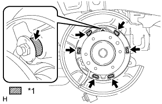
Apply a light coat of high-temperature grease to the areas of the backing plate which make contact with the shoe as shown in the illustration.
| *1 | High-temperature grease |
PARKING BRAKE ASSEMBLY > REASSEMBLY |
| 1. INSTALL PARKING BRAKE SHOE HOLD DOWN SPRING PIN |
Install the parking brake shoe hold down spring pin (for front side).
Install the parking brake shoe hold down spring pin (for rear side).
| 2. APPLY HIGH-TEMPERATURE GREASE |
|
Apply a light coat of high-temperature grease to the areas of the backing plate which make contact with the shoe as shown in the illustration.
| *1 | High-temperature grease |
| 3. INSTALL PARKING BRAKE SHOE LEVER |
Apply a light coat of high-temperature grease to the areas of the parking brake shoe lever which make contact with the No. 2 parking brake shoe assembly.
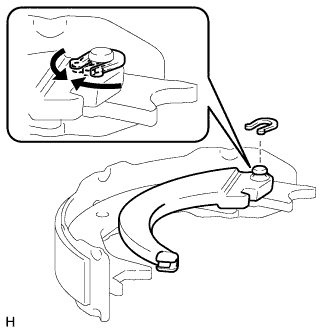 |
Install the parking brake shoe lever and shim to the No. 2 parking brake shoe assembly with a new C-washer as shown in the illustration.
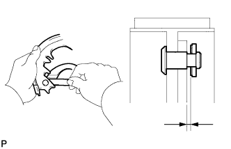 |
Using a feeler gauge, measure the clearance between the No. 2 parking brake shoe assembly and parking brake shoe lever.
| Thickness | Thickness |
| 0.2 mm (0.00787 in.) | 0.5 mm (0.0197 in.) |
| 0.3 mm (0.0118 in.) | 0.6 mm (0.0236 in.) |
| 0.4 mm (0.0157 in.) | 0.9 mm (0.0354 in.) |
| 4. INSTALL NO. 2 PARKING BRAKE SHOE ASSEMBLY WITH PARKING BRAKE SHOE LEVER |
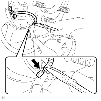 |
Using needle-nose pliers, connect the No. 3 parking brake cable assembly to the parking brake shoe lever as shown in the illustration.
| 5. INSTALL PARKING BRAKE SHOE RETURN TENSION SPRING |
Install the parking brake shoe return tension spring to the No. 2 parking brake shoe assembly.
| 6. INSTALL NO. 1 PARKING BRAKE SHOE ASSEMBLY LH |
Connect the parking brake shoe return tension spring to install the No. 1 parking brake shoe assembly.
| 7. INSTALL PARKING BRAKE SHOE ADJUSTING SCREW SET |
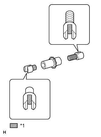 |
Apply a light coat of high-temperature grease to the areas of the shoe adjusting screw set shown in the illustration.
| *1 | High-temperature grease |
Install the parking brake shoe adjusting screw set.
| 8. INSTALL NO. 2 PARKING BRAKE SHOE ASSEMBLY LH |
Install the No. 2 parking brake shoe assembly to the backing plate with the parking brake shoe hold down spring cup and parking brake shoe hold down spring.
| 9. INSTALL PARKING BRAKE SHOE STRUT |
Install the parking brake shoe strut and parking brake shoe strut compression spring.
| 10. INSTALL NO. 1 PARKING BRAKE SHOE ASSEMBLY LH |
Install the No. 1 parking brake shoe assembly to the backing plate with the parking brake shoe hold down spring cup and parking brake shoe hold down spring.
| 11. INSTALL PARKING BRAKE SHOE RETURN TENSION SPRING |
Install the 2 parking brake shoe return tension springs.
| 12. CHECK PARKING BRAKE INSTALLATION |
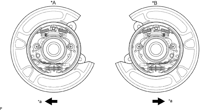
| *A | LH | *B | RH |
| *a | Front | - | - |
Check that each part is installed properly.
| 13. INSTALL REAR DISC |
Align the matchmarks and install the rear disc.
| 14. CONNECT REAR DISC BRAKE CYLINDER ASSEMBLY LH |
Connect the rear disc brake cylinder with the 2 bolts.
| 15. ADJUST PARKING BRAKE SHOE CLEARANCE AND PARKING BRAKE PEDAL TRAVEL |
Remove the lower instrument panel finish panel sub-assembly (Click here).
Completely release the parking brake pedal.
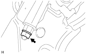 |
Loosen the lock nut and adjusting nut to completely release the parking brake cable.
Temporarily install the hub nuts to the hub bolts.
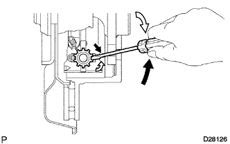 |
Turn the shoe adjuster so that it expands until the disc locks.
 | Shoe Adjuster Contracts |
 | Shoe Adjuster Expands |
Turn the shoe adjuster so that it contracts until the disc can rotate smoothly.
Check that there is no brake drag against the shoe.
 |
Turn the adjusting nut until the parking brake pedal travel is corrected to be within the specified range.
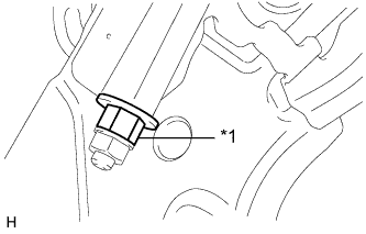
| *1 | Adjusting Nut |
Using a wrench or an equivalent tool, hold the adjusting nut and tighten the lock nut.
Operate the parking brake pedal 3 to 4 times and check the parking brake pedal travel.
Check that there is no brake drag against the shoe.
Additionally, excessive pedal travel can be adjusted on the No. 1 parking brake cable as follows.
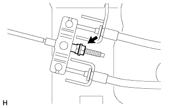 |
Loosen the No. 1 parking brake cable lock nut.
Turn the No. 1 parking brake cable adjustment nut until the parking brake pedal travel is correct.
Tighten the No. 1 parking brake cable lock nut.
Depress and release the parking brake pedal 3 or 4 times. Then check the number of clicks when depressing the pedal.
Remove the hub nuts from the hub bolts.
Install the lower instrument panel finish panel sub-assembly (Click here).
When operating the parking brake lever, check that the brake warning light comes on.
| 16. INSPECT PARKING BRAKE PEDAL TRAVEL |
Fully depress the parking brake pedal to engage the parking brake.
Depress the pedal again to disengage the parking brake.
Slowly depress the parking brake pedal using the specified force and count the number of clicks.
| 17. INSTALL REAR WHEEL |
| 18. SETTLE PARKING BRAKE SHOE AND DISC |
Drive the vehicle for approximately 400 m (0.25 miles) under the following conditions.
The vehicle speed is approximately 50 km/h (31 mph) and the vehicle is on a safe, level and dry road.
The parking brake pedal is being depressed with a force of 150 N (15 kgf, 33.7 ldf).