Install the 6 bolts <E> and nut <F>.
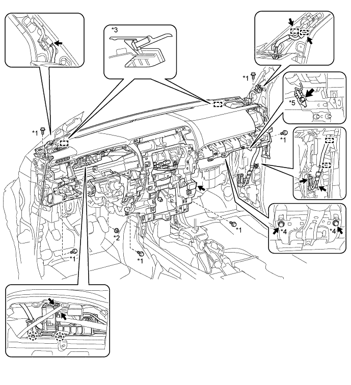
| *1 | Bolt <E> | *2 | Nut <F> |
| *3 | Guide | *4 | Passenger Airbag Bolt |
| *5 | Bolt A | - | - |
INSTRUMENT PANEL SAFETY PAD > INSTALLATION |
| 1. INSTALL INSTRUMENT PANEL SUB-ASSEMBLY |
Attach the 2 guides to install the instrument panel sub-assembly.
Connect each connector and attach the clamps and claws.
Install the 2 passenger airbag bolts.
Install the bolt labeled A.
Install the 6 bolts <E> and nut <F>.
| *1 | Bolt <E> | *2 | Nut <F> |
| *3 | Guide | *4 | Passenger Airbag Bolt |
| *5 | Bolt A | - | - |
| 2. INSTALL 4 WHEEL DRIVE CONTROL ECU NO. 2 (for 4WD) |
for VF2A:
Install the 4 wheel drive control ECU No. 2 .
for VF2BM:
Install the 4 wheel drive control ECU No. 2 .
for VF4BM:
Install the 4 wheel drive control ECU No. 2 .
| 3. INSTALL DCM (TELEMATICS TRANSCEIVER) |
Insert the DCM (telematics transceiver) with bracket into the vehicle.
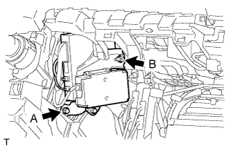 |
Install the DCM (telematics transceiver) with bracket with the bolt and nut.
Connect the connectors.
| 4. INSTALL FRONT NO. 2 SPEAKER ASSEMBLY |
Connect the connector.
Align the positioning pins of the front No. 2 speaker assembly with the instrument panel sub-assembly to temporarily install the front No. 2 speaker assembly.
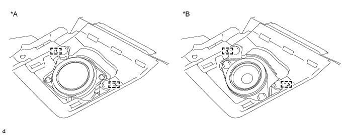
| *A | for 9 Speakers | *B | for 8 Speakers |
Install the front No. 2 speaker assembly with the 2 screws.
| 5. INSTALL NO. 1 INSTRUMENT PANEL SPEAKER PANEL SUB-ASSEMBLY |
Attach the 2 clips, 4 claws and 3 guides to install the No. 1 instrument panel speaker panel sub-assembly.
| 6. INSTALL NO. 2 INSTRUMENT PANEL SPEAKER PANEL SUB-ASSEMBLY |
Attach the 2 clips, 3 claws and 3 guides to install the No. 2 instrument panel speaker panel sub-assembly.
| 7. INSTALL NO. 1 INSTRUMENT PANEL REGISTER ASSEMBLY |
Attach the 4 clips and 2 guides to install the No. 1 instrument panel register assembly.
| 8. INSTALL NO. 2 INSTRUMENT PANEL REGISTER ASSEMBLY |
| 9. INSTALL LOWER CENTER INSTRUMENT CLUSTER FINISH PANEL SUB-ASSEMBLY (w/o Climate Control Seat System) |
Connect 2 connectors.
Attach the 4 clips to install the lower center instrument cluster finish panel sub-assembly.
Install the 2 screws <B>.
| 10. INSTALL LOWER CENTER INSTRUMENT CLUSTER FINISH PANEL SUB-ASSEMBLY (w/ Climate Control Seat System) |
Connect 3 connectors.
Attach the 4 clips to install the lower center instrument cluster finish panel sub-assembly.
Install the 2 screws <B>.
| 11. INSTALL NAVIGATION RECEIVER ASSEMBLY WITH BRACKETS (for Navigation Receiver Type) |
Connect each connector.
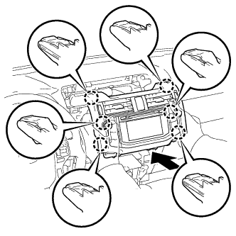 |
Insert the navigation receiver assembly with brackets to attach the 6 claws on its backside.
Install the navigation receiver assembly with brackets with the 4 bolts.
| 12. INSTALL RADIO AND DISPLAY RECEIVER ASSEMBLY WITH BRACKETS (for Radio and Display Type) |
Connect each connector.
|
Insert the radio and display receiver assembly with brackets to attach the 6 claws on its backside.
Install the radio and display receiver assembly with brackets with the 4 bolts.
| 13. INSTALL HEATER CONTROL ASSEMBLY |
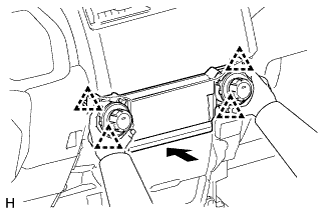 |
Attach the 4 clips to install the heater control assembly.
| 14. INSTALL LOWER INSTRUMENT PANEL SUB-ASSEMBLY |
Connect each connector.
Attach the 10 clips and guide to install the lower instrument panel sub-assembly.
Install the 3 screws <B> and 2 bolts <C>.
| 15. INSTALL INSTRUMENT PANEL BOX DOOR COVER |
Attach the 2 claws and 2 guides to install the instrument panel box door cover.
| 16. INSTALL LOWER NO. 2 INSTRUMENT PANEL AIRBAG ASSEMBLY |
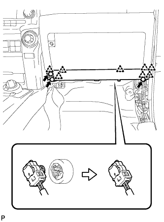 |
Connect the connector.
Attach the 8 claws to install the instrument panel airbag.
Install the 3 bolts.
| 17. INSTALL LOWER INSTRUMENT COVER LH |
Attach the 4 claws to install the lower instrument cover LH.
| 18. INSTALL NO. 2 INSTRUMENT PANEL UNDER COVER SUB-ASSEMBLY |
Attach the 3 clips and 2 guides to install the No. 2 instrument panel under cover sub-assembly.
| 19. INSTALL LOWER NO. 1 INSTRUMENT PANEL AIRBAG ASSEMBLY |
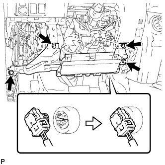 |
Connect the connector.
Install the airbag assembly with the 4 bolts.
| 20. INSTALL LOWER INSTRUMENT PANEL FINISH PANEL SUB-ASSEMBLY |
Connect each connector and hood lock control cable assembly.
Attach the 13 clips and 2 guides to install the lower instrument panel finish panel sub-assembly.
Install the 2 bolts <C>.
Attach the 2 claws to close the cover.
| 21. INSTALL COMBINATION METER ASSEMBLY |
Connect the connectors.
Install the combination meter with the 4 screws.
| 22. INSTALL INSTRUMENT CLUSTER FINISH PANEL SUB-ASSEMBLY |
Attach the 7 clips to install the instrument cluster finish panel sub-assembly.
| 23. INSTALL NO. 2 SWITCH HOLE BASE |
Connect each connector.
Attach the 6 clips and 2 guides to install the No. 2 switch hole base.
| 24. INSTALL LOWER INSTRUMENT PANEL FINISH PANEL ASSEMBLY |
w/o Smart Key System:
Connect the cooler thermistor.
Attach the 4 clips to install the lower instrument panel finish panel assembly.
w/ Smart Key System:
Connect the connector and cooler thermistor.
Attach the 4 clips to install the lower instrument panel finish panel assembly.
| 25. INSTALL FRONT PILLAR GARNISH LH |
Remove the protective cover.
Attach the 2 guides and clip to install the front pillar garnish LH.
Install the bolt.
Attach the 2 claws to install the No. 1 front pillar garnish cover LH.
| 26. INSTALL FRONT PILLAR GARNISH RH |
Remove the protective cover.
Attach the clip and 3 guides to install the front pillar garnish RH.
| 27. INSTALL NO. 1 ASSIST GRIP |
Attach the 2 claws to install the No. 1 assist grip.
Install the 2 bolts.
| 28. INSTALL ASSIST GRIP PLUG |
Attach the 2 claws to install the assist grip plug.
| 29. INSTALL FRONT DOOR OPENING TRIM WEATHERSTRIP LH |
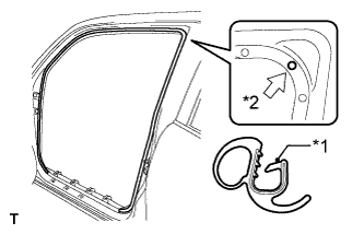 |
Align the paint mark on the front door opening trim weatherstrip LH with the mark position on the vehicle to install the front door opening trim weatherstrip LH as shown in the illustration.
| *1 | Paint Mark |
| *2 | Mark Position |
| 30. INSTALL FRONT DOOR OPENING TRIM WEATHERSTRIP RH |
| 31. INSTALL COWL SIDE TRIM BOARD LH |
Attach the clip and claw to install the cowl side trim board LH.
Install the clip.
| 32. INSTALL COWL SIDE TRIM BOARD RH |
| 33. INSTALL DOOR SCUFF PLATE ASSEMBLY LH |
Attach the 4 clips, 10 claws and 2 guides to install the door scuff plate assembly LH.
| 34. INSTALL DOOR SCUFF PLATE ASSEMBLY RH |
| 35. INSTALL REAR CONSOLE BOX ASSEMBLY |
| 36. INSTALL HEADLIGHT DIMMER SWITCH ASSEMBLY |
| 37. CONNECT CABLE TO NEGATIVE BATTERY TERMINAL |
| 38. CHECK SRS WARNING LIGHT |