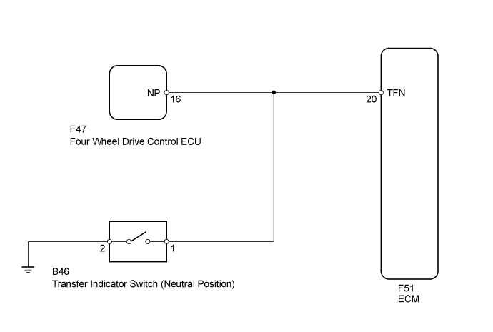
DTC P0818 Driveline Disconnect Switch Input Circuit |
| DTC Code | DTC Detection Condition | Trouble Area |
| P0818 | The signal indicating that the transfer is in neutral remains ON while the vehicle is being driven under the following conditions for 30 sec. (2-trip detection logic):
|
|
| Related DTCs | P0818: Transfer neutral position switch/Verify switch cycling |
| Required sensors/Components | Transfer neutral position switch, Vehicle speed sensor |
| Frequency of operation | Continuous |
| Duration | 30 sec. |
| MIL operation | 2 driving cycles |
| Sequence of operation | None |
| The monitor will run whenever the following DTCs are not stored | None |
| Vehicle speed | 25 km/h (15.54 mph) or more |
| Transfer | High |
| Battery voltage | 8 V or higher |
| Ignition switch | ON |
| Starter | OFF |
| Transfer neutral switch signal | ON |
| 1.INSPECT TRANSFER INDICATOR SWITCH (NEUTRAL POSITION) |
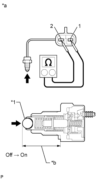 |
Remove the transfer indicator switch (neutral position) (Click here).
Measure the resistance according to the value(s) in the table below.
| Tester Connection | Condition | Specified Condition |
| 1 - 2 | Not pushed | 10 kΩ or higher |
| 1 - 2 | Pushed | Below 1 Ω |
| *1 | Ball |
| *a | Component without harness connected (Transfer Indicator Switch (Neutral Position)) |
| *b | 27 +/-0.82 mm (1.06 +/-0.0323 in.) |
 | Push |
|
| ||||
| OK | |
 |
| 2.CHECK HARNESS AND CONNECTOR (FOUR WHEEL DRIVE CONTROL ECU - BODY GROUND) |
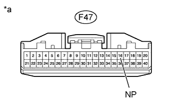 |
Disconnect the F47 four wheel drive control ECU connector.
Disconnect the B46 transfer indicator switch (neutral position) connector.
Measure the resistance according to the value(s) in the table below.
| Tester Connection | Condition | Specified Condition |
| F47-16 (NP) - Body ground | Always | 10 kΩ or higher |
| *a | Front view of wire harness connector (to Four Wheel Drive Control ECU) |
|
| ||||
| OK | ||
 | ||
| ||
| 3.CHECK HARNESS AND CONNECTOR (TRANSFER INDICATOR SWITCH (NEUTRAL POSITION), FOUR WHEEL DRIVE CONTROL ECU - ECM) |
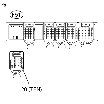 |
Disconnect the F51 ECM connector.
Disconnect the B46 transfer indicator switch (neutral position) connector.
Disconnect the F47 four wheel drive control ECU connector.
Measure the resistance according to the value(s) in the table below.
| Tester Connection | Condition | Specified Condition |
| F51-20 (TFN) - Body ground | Always | 10 kΩ or higher |
| *a | Rear view of wire harness connector (to ECM) |
|
| ||||
| OK | ||
| ||
| ||

