 |
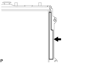
Install the No. 1 radiator to support seal to the radiator assembly as shown in the illustration.
RADIATOR > INSTALLATION |
| 1. INSTALL NO. 1 RADIATOR TO SUPPORT SEAL |
|
Install the No. 1 radiator to support seal to the radiator assembly as shown in the illustration.
| 2. INSTALL NO. 2 RADIATOR TO SUPPORT SEAL |
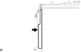 |
Install the No. 2 radiator to support seal to the radiator assembly as shown in the illustration.
| 3. INSTALL RADIATOR ASSEMBLY |
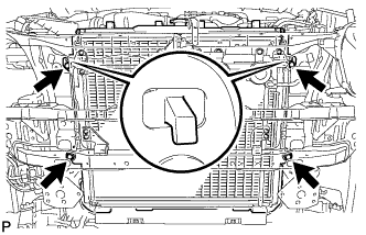 |
Insert the radiator bracket hooks into the radiator support holes.
Install the radiator with the 4 bolts.
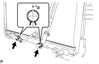 |
Connect the 2 oil cooler hoses and slide the 2 clamps to secure them.
| *a | Upper |
| 4. INSTALL FAN SHROUD |
Install the fan pulley to the water pump.
Place the fan shroud together with the coupling fan between the radiator and engine.
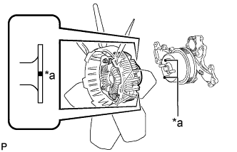 |
Align the paint marks on the heads of the water pump stud bolts with the paint marks of the same color on the outer edge of the fluid coupling flange and install the fluid coupling to the water pump.
| *a | Paint Mark |
Temporarily install the fan with fluid coupling to the water pump with the 4 nuts. Tighten the nuts as much as possible by hand.
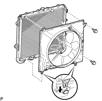 |
Attach the claws of the shroud to the radiator as shown in the illustration.
Install the fan shroud with the 2 bolts.
Install the fan with fluid coupling and generator V-belt (Click here).
Tighten the 4 nuts of the fan with fluid coupling.
| 5. CONNECT OIL COOLER TUBE |
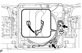 |
Connect the oil cooler tube with the 2 bolts, and attach the claw to close the flexible hose clamp.
| 6. INSTALL RADIATOR RESERVOIR TANK |
Install the radiator reservoir tank with the 3 bolts.
Connect the reservoir hose to upper side of the radiator tank upper.
| 7. INSTALL NO. 2 RADIATOR HOSE |
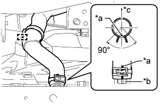 |
Connect the No. 2 radiator hose with the clamp so that its paint mark aligns with the radiator protrusion as shown in the illustration.
| *a | Paint Mark |
| *b | Protrusion |
| *c | Upper |
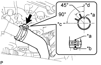 |
Connect the No. 2 radiator hose with the clamp so that its paint mark aligns with the water inlet housing protrusion as shown in the illustration.
| *a | Paint Mark |
| *b | Protrusion |
| *c | Front |
| *d | Upper |
| 8. INSTALL NO. 1 RADIATOR HOSE |
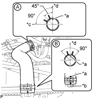 |
Connect the No. 1 radiator hose to the water inlet housing with the clamp shown in the illustration labeled A.
| *a | Paint Mark |
| *b | Protrusion |
| *c | Front |
| *d | Upper |
Connect the No. 1 radiator hose with the clamp so that its paint mark aligns with the radiator protrusion as shown in the illustration labeled B.
| 9. INSTALL RADIATOR SIDE DEFLECTOR LH |
Attach the 3 claws.
Install the radiator side deflector LH with the clip.
| 10. INSTALL RADIATOR SIDE DEFLECTOR RH |
Attach the 3 claws.
Install the radiator side deflector RH with the clip.
| 11. INSTALL UPPER FRONT BUMPER RETAINER |
Install the upper front bumper retainer with the 3 bolts and 2 screws.
| 12. INSTALL FRONT BUMPER COVER |
| 13. ADD ENGINE COOLANT |
Tighten the cylinder block drain cock plug.
Tighten the radiator drain cock plug by hand.
Add engine coolant.
Slowly pour coolant into the radiator reservoir until it reaches the F line.
Install the reservoir cap.
Install the radiator cap.*1
Start the engine and stop it immediately.*2
Allow approximately 10 seconds to pass. Then remove the radiator cap and check the coolant level. If the coolant level has decreased, add coolant.*3
Repeat steps *1, *2 and *3 until the coolant level does not decrease.
Install the radiator cap.*4
Set the air conditioning as follows.*5
| Item | Condition |
| Fan speed | Any setting except off |
| Temperature | Toward WARM |
| Air conditioning switch | Off |
Start the engine, warm it up until the thermostat opens, and then continue to run the engine for several minutes to circulate the coolant.*6
Stop the engine, wait until the engine coolant cools down to ambient temperature. Then remove the radiator cap and check the coolant level.*7
If the coolant level has decreased, add coolant and warm up the engine until the thermostat opens.*8
If the coolant level has not decreased, check that the coolant level in the radiator reservoir is at the F line.
If the coolant level is below the F line, repeat steps *4 through *8.
If the coolant level is above the F line, drain coolant until the coolant level reaches the F line.
| 14. INSPECT FOR ENGINE COOLANT LEAK |
Fill the radiator with engine coolant, and then attach a radiator cap tester.
Warm up the engine.
Using the radiator cap tester, increase the pressure inside the radiator to 123 kPa (1.3 kgf/cm2, 18 psi), and then check that the pressure does not drop.
If the pressure drops, check the hoses, radiator and water pump for leakage. If there are no signs or traces of external engine coolant leakage, check the heater core, cylinder block and head.
| 15. INSTALL NO. 1 ENGINE UNDER COVER SUB-ASSEMBLY |
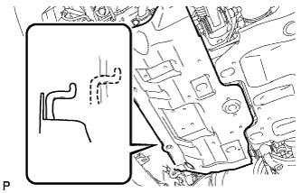 |
Hook the No. 1 engine under cover sub-assembly to the vehicle body as shown in the illustration.
Install the 4 bolts.
| 16. INSTALL FRONT LOWER BUMPER COVER (w/o Intuitive Parking Assist System) |
Install the front lower bumper cover with the 5 bolts and clip.
| 17. INSTALL AIR INTAKE DUCT LH (w/ Intuitive Parking Assist System) |
Install the air intake duct LH with the 2 screws.
Install the clip and bolt.
| 18. INSTALL AIR INTAKE DUCT RH (w/ Intuitive Parking Assist System) |
| 19. INSTALL FRONT LOWER BUMPER COVER (w/ Intuitive Parking Assist System) |
Install the front lower bumper cover with the 4 bolts and clip.
| 20. INSTALL COOL AIR INTAKE DUCT (for 4WD with Intuitive Parking Assist System) |
Install the cool air intake duct with the 4 clips.
| 21. INSTALL V-BANK COVER |
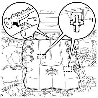 |
Attach the 2 V-bank cover hooks to the bracket. Then align the 2 V-bank cover grommets with the 2 pins and press down on the V-bank cover to attach the pins.
| *1 | Pin |
| *2 | V-bank Cover Hook |
| 22. INSTALL UPPER RADIATOR SUPPORT SEAL |
Install the upper radiator support seal with the 13 clips.