 |
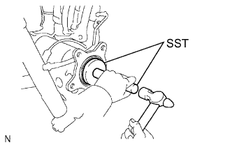
Using SST and a hammer, install a new axle shaft oil seal.
- SST
- 09950-60020
(09951-00770)
09950-70010 (09951-07150)
- NOTICE:
- Do not allow foreign matter, etc. to contact the axle shaft housing hole.
REAR AXLE SHAFT > INSTALLATION |
| 1. INSTALL REAR AXLE SHAFT OIL SEAL LH |
|
Using SST and a hammer, install a new axle shaft oil seal.
| 2. INSTALL REAR AXLE SHAFT WITH PARKING BRAKE PLATE LH |
Install a new O-ring to the axle housing.
Install the rear axle shaft with parking brake plate with the 4 nuts.
| 3. INSTALL PARKING BRAKE ASSEMBLY |
Install the parking brake assembly (Click here).
| 4. INSTALL REAR SPEED SENSOR LH |
Install the speed sensor with the nut.
Connect the speed sensor connector.
| 5. CONNECT REAR FLEXIBLE HOSE LH |
Connect the rear flexible hose to the connecting point with the brake tube, and then install a new clip.
Using a union nut wrench, connect the brake tube to the rear flexible hose while holding the rear flexible hose with a wrench.
Install the rear flexible hose and a new gasket to the rear disc brake cylinder with the union bolt.
| 6. FILL RESERVOIR WITH BRAKE FLUID |
| 7. BLEED BRAKE LINE |
Turn the engine switch on (IG).
Remove the brake master cylinder reservoir filler cap assembly.
Add brake fluid until the fluid level is between the MIN and MAX lines of the reservoir.
Repeatedly depress the brake pedal and bleed air from the bleeder plug of the front disc brake cylinder RH.
Repeat the step above until the air is completely bled, and then tighten the bleeder plug while depressing the brake pedal.
Bleed the air from the bleeder plug of the front disc brake cylinder LH using the same procedure as for the RH side.
With the brake pedal depressed, loosen the bleeder plug of the rear disc brake cylinder RH, continue to hold the brake pedal and allow brake fluid to be drained from the bleeder plug while the pump motor operates.
When there is no more air in the brake fluid, tighten the bleeder plug, and then release the brake pedal.
Bleed the air from the bleeder plug of the rear disc brake cylinder LH using the same procedure as for the RH side.
Turn the engine switch off (IG).
Inspect for brake fluid leaks.
Check and adjust the brake fluid level .
| 8. CHECK BRAKE FLUID LEVEL IN RESERVOIR |
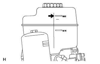 |
Turn the engine switch off and fully depress the brake pedal 40 times or more to release the pressure in the accumulator.
Adjust the fluid level so that it is at the MAX line.
| 9. INSPECT FOR BRAKE FLUID LEAK |
| 10. CONNECT CABLE TO NEGATIVE BATTERY TERMINAL |
| 11. INSTALL REAR WHEEL |
| 12. INSPECT PARKING BRAKE PEDAL TRAVEL |
Fully depress the parking brake pedal to engage the parking brake.
Depress the pedal again to disengage the parking brake.
Slowly depress the parking brake pedal using the specified force and count the number of clicks.
| 13. CHECK SPEED SENSOR SIGNAL |
Check the speed sensor signal (Click here).