Home › Power Source / Network › NETWORKING › CAN COMMUNICATION SYSTEM

CAN COMMUNICATION SYSTEM > TERMINALS OF ECU

for Preparation Click here


HINT:
Operating the ignition switch, any switches or any doors triggers related ECU and sensor communication with the CAN, which causes resistance variation.


DISCONNECT CABLE FROM NEGATIVE BATTERY TERMINAL
  1. Disconnect the cable from the negative (-) battery terminal before measuring the resistances of the main wire and branch wire.

    CAUTION:
    Wait at least 90 seconds after disconnecting the cable from the negative (-) battery terminal to disable the SRS system.

    NOTICE:
    1. Before measuring the resistance, leave the vehicle for at least a minute and do not operate the ignition switch, any switches or any doors. If doors need to be opened in order to check connectors, open the doors and leave them open.
    2. When disconnecting the cable some systems need to be initialized after the cable is reconnected (Click here).


JUNCTION CONNECTOR


  1. NO. 1 JUNCTION CONNECTOR
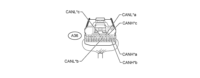

    C219177E01


    Text in Illustration 
    *a
    for Skid Control ECU (Master Cylinder Solenoid)
    *b
    for No. 2 Junction Connector
    *c
    for Combination Meter Assembly
    -
    -

    No. 1 Junction Connector
    Wiring Color
    Connect to
    A36-1 (CANH)
    B
    Skid control ECU (master cylinder solenoid)
    A36-4 (CANL)
    W
    A36-2 (CANH)
    GR
    No. 2 junction connector
    A36-5 (CANL)
    W
    A36-3 (CANH)
    L
    Combination meter assembly
    A36-6 (CANL)
    W


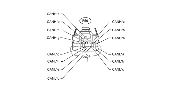
  2. NO. 2 JUNCTION CONNECTOR


    1. V1 bus:


      C219179E01


      Text in Illustration 
      *a
      for No. 4 Junction Connector
      *b
      for Main Body ECU (Multiplex Network Body ECU)
      *c
      for No. 1 Junction Connector
      *d
      for DLC3
      *e
      for Airbag Sensor Assembly
      *f
      for Stabilizer Control ECU (w/ Kinetic Dynamic Suspension System)
      *g
      for Steering Angle Sensor (Spiral Cable Sub-assembly)
      -
      -

      No. 2 Junction Connector
      Wiring Color
      Connect to
      F59-1 (CANH)
      SB
      No. 4 junction connector
      F59-12 (CANL)
      W
      F59-2 (CANH)
      R
      Main body ECU (multiplex network body ECU)
      F59-13 (CANL)
      W
      F59-3 (CANH)
      GR
      No. 1 junction connector
      F59-14 (CANL)
      W
      F59-4 (CANH)
      V
      DLC3
      F59-15 (CANL)
      W
      F59-5 (CANH)
      Y
      Airbag sensor assembly
      F59-16 (CANL)
      W
      F59-6 (CANH)
      P
      Stabilizer control ECU*1
      F59-17 (CANL)
      W
      F59-7 (CANH)
      G
      Steering angle sensor (spiral cable sub-assembly)
      F59-18 (CANL)
      W
      1. *1: w/ Kinetic Dynamic Suspension System


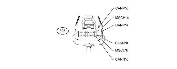
    2. MS bus (w/ Seat Position Memory):


      C219177E04


      Text in Illustration 
      *a
      for Main Body ECU (Multiplex Network Body ECU)
      *b
      for Combination Meter Assembly
      *c
      for Front Power Seat Switch LH
      -
      -

      No. 2 Junction Connector
      Wiring Color
      Connect to
      F93-1 (CANP)
      B
      Main body ECU (multiplex network body ECU)
      F93-12 (CANN)
      W
      F93-2 (MSCH)
      LG
      Combination meter assembly
      F93-13 (MSCL)
      W
      F93-3 (CANP)
      L
      Front power seat switch LH
      F93-14 (CANN)
      W


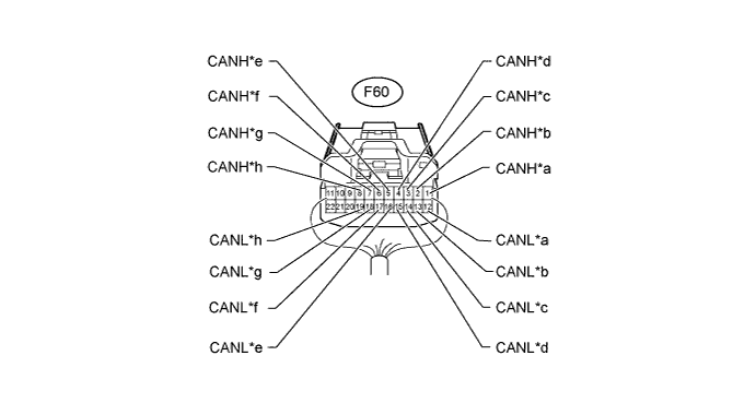
  3. NO. 3 JUNCTION CONNECTOR


    1. V1 bus:


      C219179E02


      Text in Illustration 
      *a
      for No. 4 Junction Connector
      *b
      for ECM
      *c
      for Four Wheel Drive Control ECU (for 4WD)
      *d
      for Power Management Control ECU (w/ Smart Key System)
      *e
      for Power Steering ECU Assembly
      *f
      for Certification ECU (Smart Key ECU Assembly) (w/ Smart Key System)
      *g
      for Yaw Rate Sensor Assembly
      *h
      for Air Conditioning Amplifier Assembly (w/o Smart Key System)

      No. 3 Junction Connector
      Wiring Color
      Connect to
      F60-1 (CANH)
      GR
      No. 4 junction connector
      F60-12 (CANL)
      W
      F60-2 (CANH)
      V
      ECM
      F60-13 (CANL)
      W
      F60-3 (CANH)
      G
      Four wheel drive control ECU*1
      F60-14 (CANL)
      W
      F60-4 (CANH)
      P
      Power management control ECU*2
      F60-15 (CANL)
      W
      F60-5 (CANH)
      L
      Power steering ECU assembly
      F60-16 (CANL)
      W
      F60-6 (CANH)
      Y
      Certification ECU (smart key ECU assembly)*2
      F60-17 (CANL)
      W
      F60-7 (CANH)
      R
      Yaw rate sensor assembly
      F60-18 (CANL)
      W
      F60-8 (CANH)
      B
      Air conditioning amplifier assembly*3
      F60-19 (CANL)
      W
      1. *1: for 4WD
      2. *2: w/ Smart Key System
      3. *3: w/o Smart Key System


    2. Power management bus (w/ Smart Key System):
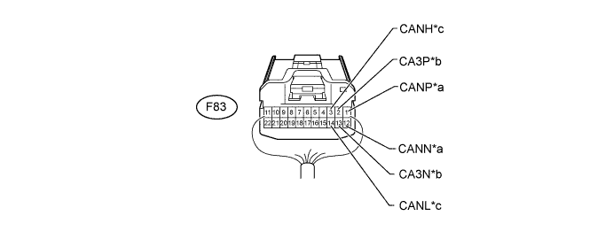

      C219177E05


      Text in Illustration 
      *a
      for ECM
      *b
      for Power Management Control ECU
      *c
      for Air Conditioning Amplifier Assembly
      -
      -

      No. 3 Junction Connector
      Wiring Color
      Connect to
      F83-1 (CANP)
      R
      ECM
      F83-12 (CANN)
      W
      F83-2 (CA3P)
      L
      Power management control ECU
      F83-13 (CA3N)
      W
      F83-3 (CANH)
      B
      Air conditioning amplifier assembly
      F83-14 (CANL)
      W


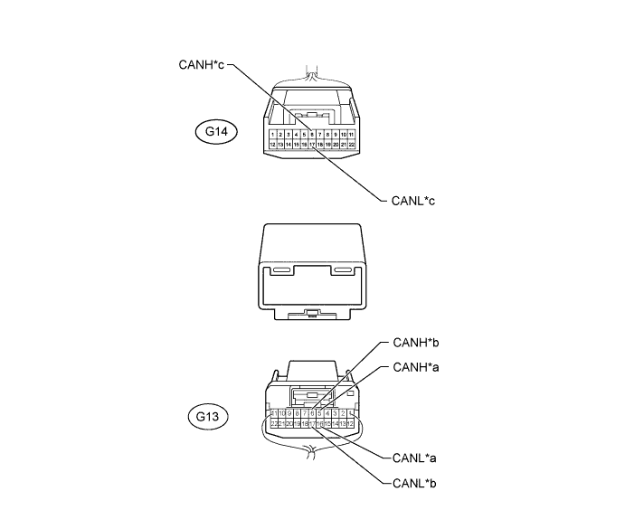
  4. NO. 4 JUNCTION CONNECTOR


    C217235E01


    Text in Illustration 
    *a
    for No. 3 Junction Connector
    *b
    for No. 2 Junction Connector
    *c
    for Navigation Receiver Assembly (for Navigation Receiver Type) or Radio and Display Receiver Assembly (for Radio and Display Receiver Type)
    -
    -

    No. 4 Junction Connector
    Wiring Color
    Connect to
    G13-5 (CANH)
    GR
    No. 3 junction connector
    G13-16 (CANL)
    W
    G13-6 (CANH)
    SB
    No. 2 junction connector
    G13-17 (CANL)
    W
    G14-6 (CANH)
    P
    Navigation receiver assembly*1
    Radio and display receiver assembly*2
    G14-17 (CANL)
    W
    1. *1: for Navigation Receiver Type
    2. *2: for Radio and Display Receiver Type
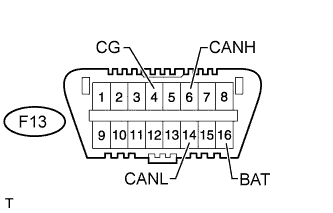

CHECK DLC3


    H102621E64
  1. Disconnect the cable from the negative (-) battery terminal before measuring the resistances of the main wire and branch wire.

    CAUTION:
    Wait at least 90 seconds after disconnecting the cable from the negative (-) battery terminal to disable the SRS system.

    NOTICE:
    When disconnecting the cable, some systems need to be initialized after the cable is reconnected (Click here).

  2. Measure the resistance according to the value(s) in the table below.

    Terminal No. (Symbol)
    Wiring Color
    Switch Condition
    Specified Condition
    F13-6 (CANH) - F13-14 (CANL)
    V - W
    Ignition switch off
    54 to 69 Ω
    F13-6 (CANH) - F13-4 (CG)
    V - W-B
    Ignition switch off
    200 Ω or higher
    F13-14 (CANL) - F13-4 (CG)
    W - W-B
    Ignition switch off
    200 Ω or higher
    F13-6 (CANH) - F13-16 (BAT)
    V - GR
    Ignition switch off
    6 kΩ or higher
    F13-14 (CANL) - F13-16 (BAT)
    W - GR
    Ignition switch off
    6 kΩ or higher


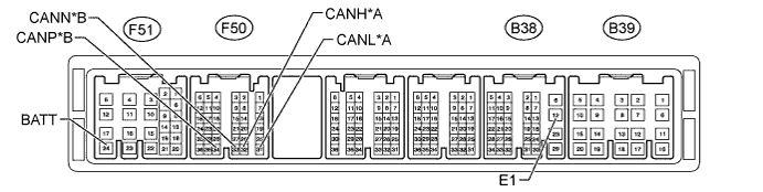
CHECK ECM

E195784E12


Text in Illustration 
*A
for V1 Bus
*B
for Power Management Bus (w/ Smart Key System)
  1. Disconnect the B38, B39, F50 and F51 ECM connectors.

  2. Measure the resistance according to the value(s) in the table below.

    for V1 Bus 
    Terminal No. (Symbol)
    Wiring Color
    Switch Condition
    Specified Condition
    F50-32 (CANH) - F50-31 (CANL)
    V - W
    Ignition switch off
    108 to 132 Ω
    F50-32 (CANH) - B38-12 (E1)
    V - BR
    Ignition switch off
    200 Ω or higher
    F50-31 (CANL) - B38-12 (E1)
    W - BR
    Ignition switch off
    200 Ω or higher
    F50-32 (CANH) - F51-24 (BATT)
    V - L
    Ignition switch off
    6 kΩ or higher
    F50-31 (CANL) - F51-24 (BATT)
    W - L
    Ignition switch off
    6 kΩ or higher

    for Power Management Bus (w/ Smart Key System) 
    Terminal No. (Symbol)
    Wiring Color
    Switch Condition
    Specified Condition
    F50-34 (CANP) - F50-33 (CANN)
    R - W
    Ignition switch off
    108 to 132 Ω
    F50-34 (CANP) - B38-12 (E1)
    R - BR
    Ignition switch off
    200 Ω or higher
    F50-33 (CANN) - B38-12 (E1)
    W - BR
    Ignition switch off
    200 Ω or higher
    F50-34 (CANP) - F51-24 (BATT)
    R - L
    Ignition switch off
    6 kΩ or higher
    F50-33 (CANN) - F51-24 (BATT)
    W - L
    Ignition switch off
    6 kΩ or higher


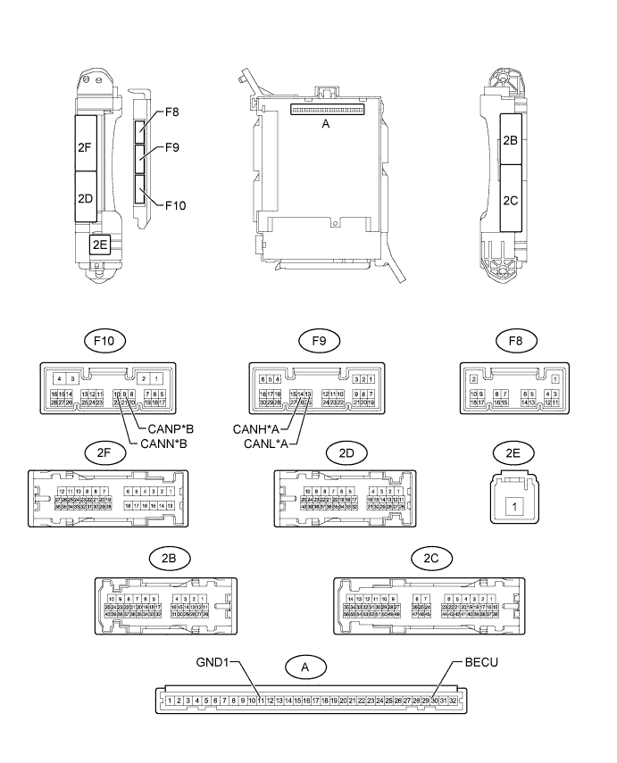
CHECK DRIVER SIDE JUNCTION BLOCK ASSEMBLY, MAIN BODY ECU (MULTIPLEX NETWORK BODY ECU)

B238680E06


Text in Illustration 
*A
for V1 Bus
*B
for MS Bus (w/ CRAWL Control or w/ Seat Position Memory)
  1. Remove the main body ECU (multiplex network body ECU) (Click here).

  2. Measure the resistance according to the value(s) in the table below.

    for V1 Bus 
    Terminal No. (Symbol)
    Wiring Color
    Switch Condition
    Specified Condition
    F9-14 (CANH) - F9-13 (CANL)
    R - W
    Ignition switch off
    54 to 69 Ω
    F9-14 (CANH) - A-11 (GND1)
    R - None
    Ignition switch off
    200 Ω or higher
    F9-13 (CANL) - A-11 (GND1)
    W - None
    Ignition switch off
    200 Ω or higher
    F9-14 (CANH) - A-30 (BECU)
    R - None
    Ignition switch off
    6 kΩ or higher
    F9-13 (CANL) - A-30 (BECU)
    W - None
    Ignition switch off
    6 kΩ or higher

    for MS Bus (w/ CRAWL Control or w/ Seat Position Memory) 
    Terminal No. (Symbol)
    Wiring Color
    Switch Condition
    Specified Condition
    F10-9 (CANP) - F10-10 (CANN)
    B - W
    Ignition switch off
    108 to 132 Ω
    F10-9 (CANP) - A-11 (GND1)
    B - None
    Ignition switch off
    200 Ω or higher
    F10-10 (CANN) - A-11 (GND1)
    W - None
    Ignition switch off
    200 Ω or higher
    F10-9 (CANP) - A-30 (BECU)
    B - None
    Ignition switch off
    6 kΩ or higher
    F10-10 (CANN) - A-30 (BECU)
    W - None
    Ignition switch off
    6 kΩ or higher


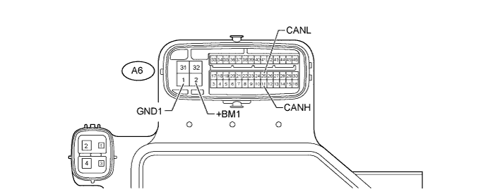
CHECK SKID CONTROL ECU (MASTER CYLINDER SOLENOID)

C212695E01

  1. Disconnect the A6 skid control ECU (master cylinder solenoid) connector.

  2. Measure the resistance according to the value(s) in the table below.

    Terminal No. (Symbol)
    Wiring Color
    Switch Condition
    Specified Condition
    A6-11 (CANH) - A6-25 (CANL)
    B - W
    Ignition switch off
    54 to 69 Ω
    A6-11 (CANH) - A6-1 (GND1)
    B - W-B
    Ignition switch off
    200 Ω or higher
    A6-25 (CANL) - A6-1 (GND1)
    W - W-B
    Ignition switch off
    200 Ω or higher
    A6-11 (CANH) - A6-2 (+BM1)
    B - B
    Ignition switch off
    6 kΩ or higher
    A6-25 (CANL) - A6-2 (+BM1)
    W - B
    Ignition switch off
    6 kΩ or higher


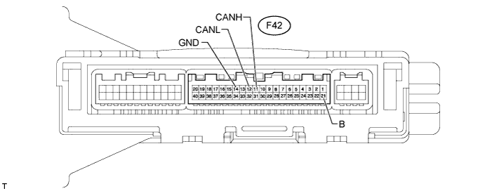
CHECK AIR CONDITIONING AMPLIFIER ASSEMBLY

C128168E09

  1. Disconnect the F42 air conditioning amplifier assembly connector.

  2. Measure the resistance according to the value(s) in the table below.

    Terminal No. (Symbol)
    Wiring Color
    Switch Condition
    Specified Condition
    F42-11 (CANH) - F42-12 (CANL)
    B - W
    Ignition switch off
    54 to 69 Ω
    F42-11 (CANH) - F42-14 (GND)
    B - W-B
    Ignition switch off
    200 Ω or higher
    F42-12 (CANL) - F42-14 (GND)
    W - W-B
    Ignition switch off
    200 Ω or higher
    F42-11 (CANH) - F42-21 (B)
    B - V
    Ignition switch off
    6 kΩ or higher
    F42-12 (CANL) - F42-21 (B)
    W - V
    Ignition switch off
    6 kΩ or higher


CHECK STABILIZER CONTROL ECU (w/ Kinetic Dynamic Suspension System)

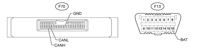
C214235E01

  1. Disconnect the F70 stabilizer control ECU connector.

  2. Measure the resistance according to the value(s) in the table below.

    Terminal No. (Symbol)
    Wiring Color
    Switch Condition
    Specified Condition
    F70-29 (CANH) - F70-28 (CANL)
    P - W
    Ignition switch off
    54 to 69 Ω
    F70-29 (CANH) - F70-22 (GND)
    P - W-B
    Ignition switch off
    200 Ω or higher
    F70-28 (CANL) - F70-22 (GND)
    W - W-B
    Ignition switch off
    200 Ω or higher
    F70-29 (CANH) - F13-16 (BAT)
    P - GR
    Ignition switch off
    6 kΩ or higher
    F70-28 (CANL) - F13-16 (BAT)
    W - GR
    Ignition switch off
    6 kΩ or higher


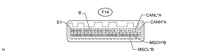
CHECK COMBINATION METER ASSEMBLY

E161130E27


Text in Illustration 
*A
for V1 Bus
*B
for MS Bus (w/ Seat Position Memory)
  1. Disconnect the F14 combination meter assembly connector.

  2. Measure the resistance according to the value(s) in the table below.

    for V1 Bus 
    Terminal No. (Symbol)
    Wiring Color
    Switch Condition
    Specified Condition
    F14-1 (CANH) - F14-2 (CANL)
    L - W
    Ignition switch off
    108 to 132 Ω
    F14-1 (CANH) - F14-20 (E1)
    L - W-B
    Ignition switch off
    200 Ω or higher
    F14-2 (CANL) - F14-20 (E1)
    W - W-B
    Ignition switch off
    200 Ω or higher
    F14-1 (CANH) - F14-15 (B)
    L - L
    Ignition switch off
    6 kΩ or higher
    F14-2 (CANL) - F14-15 (B)
    W - L
    Ignition switch off
    6 kΩ or higher

    for MS Bus (w/ Seat Position Memory) 
    Terminal No. (Symbol)
    Wiring Color
    Switch Condition
    Specified Condition
    F14-23 (MSCH) - F14-24 (MSCL)
    LG - W
    Ignition switch off
    108 to 132 Ω
    F14-23 (MSCH) - F14-20 (E1)
    LG - W-B
    Ignition switch off
    200 Ω or higher
    F14-24 (MSCL) - F14-20 (E1)
    W - W-B
    Ignition switch off
    200 Ω or higher
    F14-23 (MSCH) - F14-15 (B)
    LG - L
    Ignition switch off
    6 kΩ or higher
    F14-24 (MSCL) - F14-15 (B)
    W - L
    Ignition switch off
    6 kΩ or higher


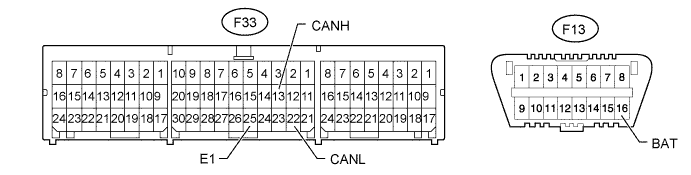
CHECK AIRBAG SENSOR ASSEMBLY

C216693E01

  1. Disconnect the F33 airbag sensor assembly connector.

  2. Measure the resistance according to the value(s) in the table below.

    Terminal No. (Symbol)
    Wiring Color
    Switch Condition
    Specified Condition
    F33-13 (CANH) - F33-22 (CANL)
    Y - W
    Ignition switch off
    54 to 69 Ω
    F33-13 (CANH) - F33-25 (E1)
    Y - W-B
    Ignition switch off
    200 Ω or higher
    F33-22 (CANL) - F33-25 (E1)
    W - W-B
    Ignition switch off
    200 Ω or higher
    F33-13 (CANH) - F13-16 (BAT)
    Y - GR
    Ignition switch off
    6 kΩ or higher
    F33-22 (CANL) - F13-16 (BAT)
    W - GR
    Ignition switch off
    6 kΩ or higher


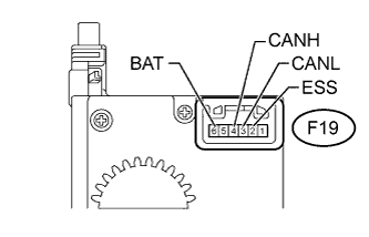
CHECK STEERING ANGLE SENSOR (SPIRAL CABLE SUB-ASSEMBLY)
C201866E03
  1. Disconnect the F19 steering angle sensor (spiral cable sub-assembly) connector.

  2. Measure the resistance according to the value(s) in the table below.

    Terminal No. (Symbol)
    Wiring Color
    Switch Condition
    Specified Condition
    F19-4 (CANH) - F19-3 (CANL)
    G - W
    Ignition switch off
    54 to 69 Ω
    F19-4 (CANH) - F19-2 (ESS)
    G - W-B
    Ignition switch off
    200 Ω or higher
    F19-3 (CANL) - F19-2 (ESS)
    W - W-B
    Ignition switch off
    200 Ω or higher
    F19-4 (CANH) - F19-6 (BAT)
    G - L
    Ignition switch off
    6 kΩ or higher
    F19-3 (CANL) - F19-6 (BAT)
    W - L
    Ignition switch off
    6 kΩ or higher


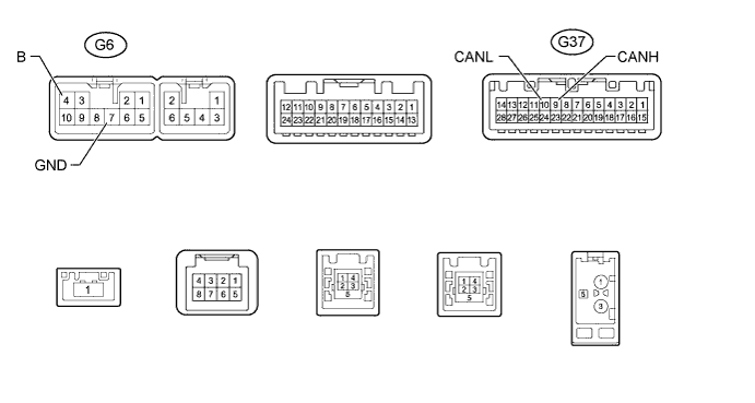
CHECK NAVIGATION RECEIVER ASSEMBLY (for Navigation Receiver Type)

E278088E04

  1. Disconnect the G6 and G37 navigation receiver assembly connectors.

  2. Measure the resistance according to the value(s) in the table below.

    Terminal No. (Symbol)
    Wiring Color
    Switch Condition
    Specified Condition
    G37-9 (CANH) - G37-10 (CANL)
    P - W
    Ignition switch off
    54 to 69 Ω
    G37-9 (CANH) - G6-7 (GND)
    P - BR
    Ignition switch off
    200 Ω or higher
    G37-10 (CANL) - G6-7 (GND)
    W - BR
    Ignition switch off
    200 Ω or higher
    G37-9 (CANH) - G6-4 (B)
    P - SB
    Ignition switch off
    6 kΩ or higher
    G37-10 (CANL) - G6-4 (B)
    W - SB
    Ignition switch off
    6 kΩ or higher


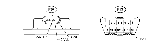
CHECK YAW RATE SENSOR ASSEMBLY

C213562E01

  1. Disconnect the F36 yaw rate sensor assembly connector.

  2. Measure the resistance according to the value(s) in the table below.

    Terminal No. (Symbol)
    Wiring Color
    Switch Condition
    Specified Condition
    F36-3 (CANH) - F36-2 (CANL)
    R - W
    Ignition switch off
    54 to 69 Ω
    F36-3 (CANH) - F36-1 (GND)
    R - W-B
    Ignition switch off
    200 Ω or higher
    F36-2 (CANL) - F36-1 (GND)
    W - W-B
    Ignition switch off
    200 Ω or higher
    F36-3 (CANH) - F13-16 (BAT)
    R - GR
    Ignition switch off
    6 kΩ or higher
    F36-2 (CANL) - F13-16 (BAT)
    W - GR
    Ignition switch off
    6 kΩ or higher


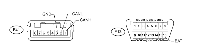
CHECK POWER STEERING ECU ASSEMBLY

C217238E02

  1. Disconnect the F41 power steering ECU assembly connector.

  2. Measure the resistance according to the value(s) in the table below.

    Terminal No. (Symbol)
    Wiring Color
    Switch Condition
    Specified Condition
    F41-1 (CANH) - F41-2 (CANL)
    L - W
    Ignition switch off
    54 to 69 Ω
    F41-1 (CANH) - F41-3 (GND)
    L - W-B
    Ignition switch off
    200 Ω or higher
    F41-2 (CANL) - F41-3 (GND)
    W - W-B
    Ignition switch off
    200 Ω or higher
    F41-1 (CANH) - F13-16 (BAT)
    L - GR
    Ignition switch off
    6 kΩ or higher
    F41-2 (CANL) - F13-16 (BAT)
    W - GR
    Ignition switch off
    6 kΩ or higher


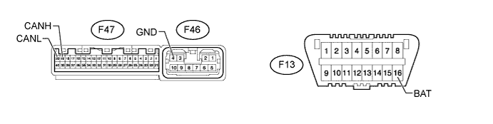
CHECK FOUR WHEEL DRIVE CONTROL ECU (for 4WD)

C213564E01

  1. Disconnect the F47 and F46 four wheel drive control ECU connectors.

  2. Measure the resistance according to the value(s) in the table below.

    Terminal No. (Symbol)
    Wiring Color
    Switch Condition
    Specified Condition
    F47-19 (CANH) - F47-20 (CANL)
    G - W
    Ignition switch off
    54 to 69 Ω
    F47-19 (CANH) - F46-4 (GND)
    G - W-B
    Ignition switch off
    200 Ω or higher
    F47-20 (CANL) - F46-4 (GND)
    W - W-B
    Ignition switch off
    200 Ω or higher
    F47-19 (CANH) - F13-16 (BAT)
    G - GR
    Ignition switch off
    6 kΩ or higher
    F47-20 (CANL) - F13-16 (BAT)
    W - GR
    Ignition switch off
    6 kΩ or higher


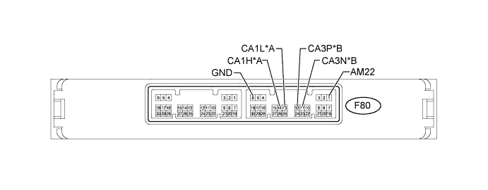
CHECK POWER MANAGEMENT CONTROL ECU (w/ Smart Key System)

C201247E06


Text in Illustration 
*A
for V1 Bus
*B
for Power Management Bus
  1. Disconnect the F80 power management control ECU connector.

  2. Measure the resistance according to the value(s) in the table below.

    for V1 Bus 
    Terminal No. (Symbol)
    Wiring Color
    Switch Condition
    Specified Condition
    F80-14 (CA1H) - F80-13 (CA1L)
    P - W
    Ignition switch off
    54 to 69 Ω
    F80-14 (CA1H) - F80-6 (GND)
    P - W-B
    Ignition switch off
    200 Ω or higher
    F80-13 (CA1L) - F80-6 (GND)
    W - W-B
    Ignition switch off
    200 Ω or higher
    F80-14 (CA1H) - F80-1 (AM22)
    P - B
    Ignition switch off
    6 kΩ or higher
    F80-13 (CA1L) - F80-1 (AM22)
    W - B
    Ignition switch off
    6 kΩ or higher

    for Power Management Bus 
    Terminal No. (Symbol)
    Wiring Color
    Switch Condition
    Specified Condition
    F80-12 (CA3P) - F80-11 (CA3N)
    L - W
    Ignition switch off
    108 to 132 Ω
    F80-12 (CA3P) - F80-6 (GND)
    L - W-B
    Ignition switch off
    200 Ω or higher
    F80-11 (CA3N) - F80-6 (GND)
    W - W-B
    Ignition switch off
    200 Ω or higher
    F80-12 (CA3P) - F80-1 (AM22)
    L - B
    Ignition switch off
    6 kΩ or higher
    F80-11 (CA3N) - F80-1 (AM22)
    W - B
    Ignition switch off
    6 kΩ or higher


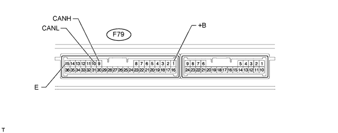
CHECK CERTIFICATION ECU (SMART KEY ECU ASSEMBLY) (w/ Smart Key System)

B197893E12

  1. Disconnect the F79 certification ECU (smart key ECU assembly) connector.

  2. Measure the resistance according to the value(s) in the table below.

    Terminal No. (Symbol)
    Wiring Color
    Switch Condition
    Specified Condition
    F79-9 (CANH) - F79-10 (CANL)
    Y - W
    Ignition switch off
    54 to 69 Ω
    F79-9 (CANH) - F79-15 (E)
    Y - W-B
    Ignition switch off
    200 Ω or higher
    F79-10 (CANL) - F79-15 (E)
    W - W-B
    Ignition switch off
    200 Ω or higher
    F79-9 (CANH) - F79-1 (+B)
    Y - V
    Ignition switch off
    6 kΩ or higher
    F79-10 (CANL) - F79-1 (+B)
    W - V
    Ignition switch off
    6 kΩ or higher


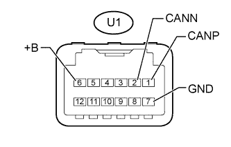
CHECK DRIVE MONITOR SWITCH (w/ CRAWL Control)
C213264E02
  1. Disconnect the U1 drive monitor switch connector.

  2. Measure the resistance according to the value(s) in the table below.

    Terminal No. (Symbol)
    Wiring Color
    Switch Condition
    Specified Condition
    U1-1 (CANP) - U1-2 (CANN)
    B - W
    Ignition switch off
    108 to 132 Ω
    U1-1 (CANP) - U1-7 (GND)
    B - W-B
    Ignition switch off
    200 Ω or higher
    U1-2 (CANN) - U1-7 (GND)
    W - W-B
    Ignition switch off
    200 Ω or higher
    U1-1 (CANP) - U1-6 (+B)
    B - L
    Ignition switch off
    6 kΩ or higher
    U1-2 (CANN) - U1-6 (+B)
    W - L
    Ignition switch off
    6 kΩ or higher


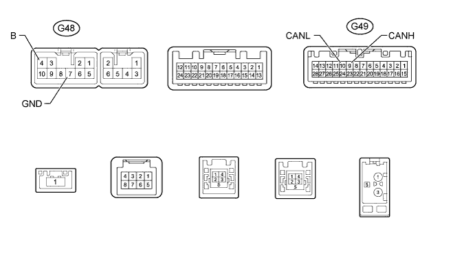
CHECK RADIO AND DISPLAY RECEIVER ASSEMBLY (for Radio and Display Receiver Type)

E278088E02

  1. Disconnect the G48 and G49 radio and display receiver assembly connectors.

  2. Measure the resistance according to the value(s) in the table below.

    Terminal No. (Symbol)
    Wiring Color
    Switch Condition
    Specified Condition
    G49-9 (CANH) - G49-10 (CANL)
    P - W
    Ignition switch off
    54 to 69 Ω
    G49-9 (CANH) - G48-7 (GND)
    P - BR
    Ignition switch off
    200 Ω or higher
    G49-10 (CANL) - G48-7 (GND)
    W - BR
    Ignition switch off
    200 Ω or higher
    G49-9 (CANH) - G48-4 (B)
    P - SB
    Ignition switch off
    6 kΩ or higher
    G49-10 (CANL) - G48-4 (B)
    W - SB
    Ignition switch off
    6 kΩ or higher


CHECK FRONT POWER SEAT SWITCH LH (w/ Seat Position Memory)

B219506E50

  1. Disconnect the b18 and b19 front power seat switch LH connectors.

  2. Measure the resistance according to the value(s) in the table below.

    Terminal No. (Symbol)
    Wiring Color
    Switch Condition
    Specified Condition
    b19-8 (CANP) - b19-7 (CANN)
    L - W
    Ignition switch off
    54 to 69 Ω
    b19-8 (CANP) - b18-2 (GND)
    L - W-B
    Ignition switch off
    200 Ω or higher
    b19-7 (CANN) - b18-2 (GND)
    W - W-B
    Ignition switch off
    200 Ω or higher
    b19-8 (CANP) - b18-7 (B)
    L - W
    Ignition switch off
    6 kΩ or higher
    b19-7 (CANN) - b18-7 (B)
    W - W
    Ignition switch off
    6 kΩ or higher