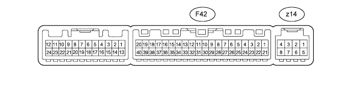
AIR CONDITIONING SYSTEM (for Automatic Air Conditioning System) > TERMINALS OF ECU |
| CHECK AIR CONDITIONING AMPLIFIER ASSEMBLY |
Disconnect the F42 amplifier connector.
Measure the voltage and resistance according to the value(s) in the table below.
| Terminal No. (Symbol) | Wiring Color | Terminal Description | Condition | Specified Condition |
| F42-21 (B) - F42-14 (GND) | V - W-B | Battery power source | Always | 11 to 14 V |
| F42-1 (IG+) - F42-14 (GND) | L - W-B | Ignition power supply | Ignition switch ON | 11 to 14 V |
| Ignition switch off | Below 1 V | |||
| F42-14 (GND) - Body ground | W-B - Body ground | Ground for main power supply | Always | Below 1 Ω |
Reconnect the F42 amplifier connector.
Measure the voltage and resistance according to the value(s) in the table below.
| Terminal No. (Symbol) | Wiring Color | Terminal Description | Condition | Specified Condition |
| F42-3 (PTC1) - Body ground*1 | V - Body ground | PTC NO. 1 relay operation signal |
| 11 to 14 V*2 |
| F42-4 (PTC3) - Body ground*1 | P - Body ground | PTC NO. 3 relay operation signal |
| 11 to 14 V*2 |
| F42-5 (TAM) - F42-13 (SG-2) | V - G | Cooler thermistor (ambient temperature sensor) signal |
| 1.35 to 1.75 V |
| F42-5 (TAM) - F42-13 (SG-2) | V - G | Cooler thermistor (ambient temperature sensor) signal |
| 0.9 to 1.2 V |
| F42-8 (LOCK) - F42-13 (SG-2) | R - G | A/C compressor lock sensor signal |
| Pulse generation (See waveform 1) |
| F42-9 (PRE) - Body Ground | G - Body Ground | No. 1 pressure switch signal |
| Below 1 V |
| F42-9 (PRE) - Body Ground | G - Body Ground | No. 1 pressure switch signal |
| 4.69 V or higher |
| F42-17 (AC1) - F42-14 (GND) | LG - W-B | Compressor operation signal |
| Below 1 V |
| F42-18 (MHTR) - F42-14 (GND) | G - W-B | MIR HTR relay signal |
| Below 1 V |
| F42-20 (MGC) - F42-14 (GND) | R - W-B | Magnet clutch assembly operation signal |
| Below 1 V |
| F42-22 (PTC2) - Body ground*1 | LG - Body ground | PTC NO. 2 relay operation signal |
| 11 to 14 V*2 |
| F42-23 (BLW) - F42-14 (GND) | LG - W-B | Blower with fan motor sub-assembly control signal |
| Pulse generation (See waveform 2) |
| F42-25 (ALT) - F42-14 (GND)*1 | L - W-B | Generator signal (PTC heater control) | Engine started | Pulse generation |
| F42-27 (ACT) - F42-14 (GND) | SB - W-B | Compressor operation signal |
| 4.75 to 5.25 V |
| F42-29 (TR) - F42-34 (SG-1) | GR - SB | Cooler thermistor (room temperature sensor) signal |
| 1.8 to 2.2 V |
| 1.2 to 1.6 V | |||
| F42-32 (TSP) - F42-14 (GND) | B - W-B | Automatic light control sensor (solar sensor) power signal (for front passenger side) |
| 0.8 to 4.3 V |
| Below 0.8 V | |||
| F42-33 (TSD) - F42-14 (GND) | GR - W-B | Automatic light control sensor (solar sensor) power signal (for driver side) |
| 0.8 to 4.3 V |
| Below 0.8 V | |||
| z14-2 (BUS G) - Body ground | - | Ground for BUS IC | Always | Below 1 V |
| z14-3 (BUS) - z14-2 (BUS G) | - | BUS IC control signal | Ignition switch ON | Pulse generation |
| z14-4 (B BUS) - z14-2 (BUS G) | - | Power supply for BUS IC | Always | 11 to 14 V |
| z14-6 (TE) - z14-5 (SG-3) | - | No. 1 cooler thermistor signal |
| 1.7 to 2.1 V |
| 0.9 to 1.3 V |
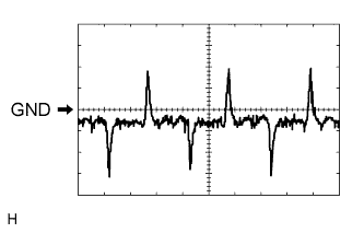 |
Using an oscilloscope, check waveform 1.
| Item | Content |
| Terminal No. (Symbol) | F42-8 (LOCK) - F42-13 (SG-2) |
| Tool Setting | 200 mV/DIV., 10 ms./DIV. |
| Condition |
|
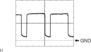 |
Using an oscilloscope, check waveform 2.
| Item | Content |
| Terminal No. (Symbol) | F42-23 (BLW) - F42-14 (GND) |
| Tool Setting | 1 V/DIV., 500 μs/DIV. |
| Condition |
|
| CHECK HEATER CONTROL ASSEMBLY |

Disconnect the F29 control connector.
Measure the resistance and voltage according to the value(s) in the table below.
| Terminal No. (Symbol) | Wiring Color | Terminal Description | Condition | Specified Condition |
| F29-4 (IG+) - F29-11 (GND) | L - W-B | IG power supply | Ignition switch ON | 11 to 14 V |
| F29-11 (GND) - Body ground | W-B - Body ground | Ground | Always | Below 1 Ω |
| CHECK DRIVER SIDE JUNCTION BLOCK ASSEMBLY AND MAIN BODY ECU (MULTIPLEX NETWORK BODY ECU) |
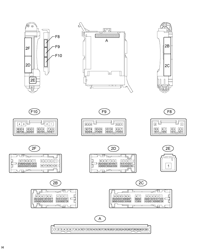
Remove the main body ECU (Click here).
Measure the voltage and resistance according to the value(s) in the table below.
| Terminal No. (Symbol) | Wiring Color | Terminal Description | Condition | Specified Condition |
| A-11 (GND1) - Body ground | - | Ground | Always | Below 1 Ω |
| A-29 (ACC) - Body ground | - | ACC power supply | Ignition switch ACC | 11 to 14 V |
| A-31 (ALTB) - Body ground | - | Battery power supply | Always | 11 to 14 V |
| A-32 (IG) - Body ground | - | Ignition switch power supply | Ignition switch ON | 11 to 14 V |
Install the main body ECU (Click here).
Measure the voltage according to the value(s) in the table below.
| Terminal No. (Symbol) | Wiring Color | Terminal Description | Condition | Specified Condition |
| F9-20 (CLTB) - Body ground | P - Body ground | Automatic light control sensor power supply output | Ignition switch off | Below 1 V |
| Ignition switch ON | 11 to 14 V | |||
| F9-22 (CLTE) - Body ground | L - Body ground | Automatic light control sensor ground | Always | Below 1 Ω |