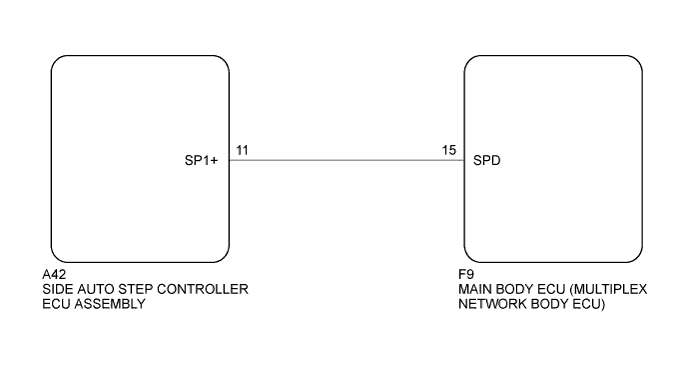
AUTOMATIC RUNNING BOARD SYSTEM > Speed Signal Circuit |
| 1.INSPECT MAIN BODY ECU (MULTIPLEX NETWORK BODY ECU) |
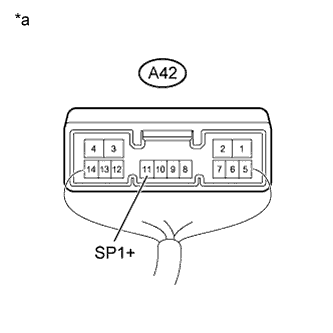 |
Measure the voltage according to the value(s) in the table below.
| Tester Connection | Condition | Specified Condition |
| A42-11 (SP1+) - Body ground | Vehicle speed at lower than 8 km/h (5 mph) | 11 to 14 V |
| Vehicle speed at 8 km/h (5 mph) or more | Below 1 V |
| *a | Component with harness connected (Side Auto Step Controller ECU Assembly) |
| Result | Proceed to |
| NG | A |
| OK | B |
|
| ||||
| A | |
 |
| 2.CHECK HARNESS AND CONNECTOR (SIDE AUTO STEP ECU - MAIN BODY ECU) |
Disconnect the A42 side auto step controller ECU assembly connector.
Disconnect the F9 main body ECU (multiplex network body ECU) connector.
Measure the resistance according to the value(s) in the table below.
| Tester Connection | Condition | Specified Condition |
| A42-11 (SP1+) - F9-15 (SPD) | Always | Below 1 Ω |
| Tester Connection | Condition | Specified Condition |
| A42-11 (SP1+) - Body ground | Always | 10 kΩ or higher |
|
| ||||
| OK | ||
 | ||
| ||
