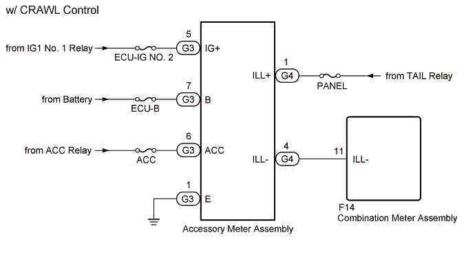
METER / GAUGE SYSTEM > Accessory Meter does not Illuminate |
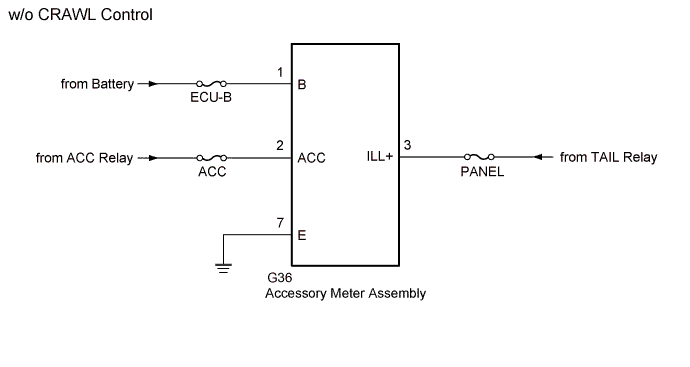
| 1.CHECK ACCESSORY METER ASSEMBLY |
Check the type of accessory meter assembly malfunction.
| Result | Proceed to |
| Accessory meter assembly does not display at all | A |
| Accessory meter assembly does not dim at night | B |
|
| ||||
| A | |
 |
| 2.CHECK HARNESS AND CONNECTOR (ACCESSORY METER ASSEMBLY CIRCUIT) |
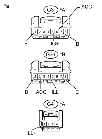 |
w/ CRAWL Control
Disconnect the G3 and G4 accessory meter assembly connectors.
Measure the voltage according to the value(s) in the table below.
| Tester Connection | Switch Condition | Specified Condition |
| G3-5 (IG+) - Body ground | Ignition switch ON | 11 to 14 V |
| G3-6 (ACC) - Body ground | Ignition switch ACC | 11 to 14 V |
| G3-7 (B) - Body ground | Always | 11 to 14 V |
| G4-1 (ILL+) - Body ground | Light control switch TAIL or HEAD | 11 to 14 V |
Measure the resistance according to the value(s) in the table below.
| Tester Connection | Condition | Specified Condition |
| G3-1 (E) - Body ground | Always | Below 1 Ω |
w/o CRAWL Control
Disconnect the G36 accessory meter assembly connector.
Measure the voltage according to the value(s) in the table below.
| Tester Connection | Switch Condition | Specified Condition |
| G36-2 (ACC) - Body ground | Ignition switch ACC | 11 to 14 V |
| G36-1 (B) - Body ground | Always | 11 to 14 V |
| G36-3 (ILL+) - Body ground | Light control switch TAIL or HEAD | 11 to 14 V |
Measure the resistance according to the value(s) in the table below.
| Tester Connection | Condition | Specified Condition |
| G36-7 (E) - Body ground | Always | Below 1 Ω |
| *A | w/ CRAWL Control |
| *B | w/o CRAWL Control |
| *a | Front view of wire harness connector (to Accessory Meter Assembly) |
|
| ||||
| OK | ||
 | ||
| ||
| 3.CHECK HARNESS AND CONNECTOR (ACCESSORY METER ASSEMBLY - COMBINATION METER ASSEMBLY) |
Disconnect the F14 combination meter assembly connector.
Disconnect the G4 accessory meter assembly connector.
Measure the resistance according to the value(s) in the table below.
| Tester Connection | Condition | Specified Condition |
| G4-4 (ILL-) - F14-11 (ILL-) | Always | Below 1 Ω |
| G4-4 (ILL-) - Body ground | Always | 10 kΩ or higher |
|
| ||||
| OK | |
|
| 4.REPLACE ACCESSORY METER ASSEMBLY |
Replace the accessory meter assembly with a new or normally functioning one (Click here).
|
| ||||
| OK | ||
| ||
| ||

